
Preparation method of carbon loaded hollow nanogold nickel alloy catalyst for direct methanol fuel cell

A methanol fuel cell, gold-nickel alloy technology, applied in the direction of metal/metal oxide/metal hydroxide catalysts, chemical instruments and methods, physical/chemical process catalysts, etc., can solve the problem of decreased resistance to methanol poisoning

Inactive Publication Date: 2014-12-24
TAIYUAN UNIV OF TECH
View PDF4 Cites 0 Cited by
  • Summary
  • Abstract
  • Description
  • Claims
  • Application Information

AI Technical Summary

Problems solved by technology

Although the Pt-based composite catalyst has better resistance to methanol poisoning than pure Pt catalysts, its resistance to methanol poisoning will decline after a long period of operation with the loss of M components in the composite catalyst.

Method used


Image

  • Preparation method of carbon loaded hollow nanogold nickel alloy catalyst for direct methanol fuel cell
  • Preparation method of carbon loaded hollow nanogold nickel alloy catalyst for direct methanol fuel cell
  • Preparation method of carbon loaded hollow nanogold nickel alloy catalyst for direct methanol fuel cell

Examples


Embodiment approach 1

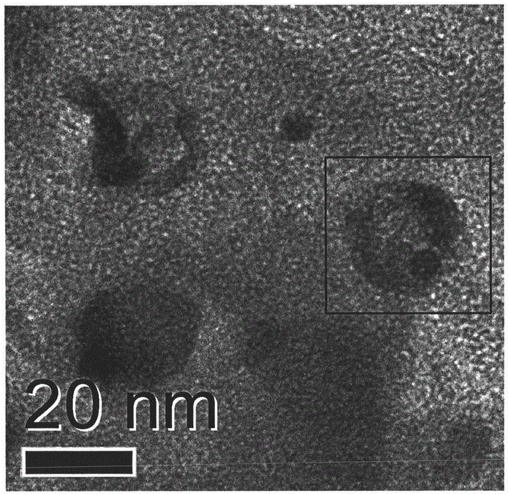
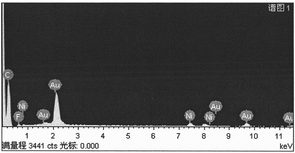
[0024] Embodiment 1: In the fourth step of the preparation process, the alloying temperature is 400° C., and the heat treatment time is 12 hours. Other preparation conditions remained unchanged. The TEM picture of the obtained catalyst is as figure 1 shown. figure 1 It was shown that the nanoparticles in the catalyst showed a clear hollow structure. figure 1 The EDS energy spectrum of the hollow nanoparticles shown in the middle box is as follows figure 2 shown. From figure 2 It can be seen that the nanoparticles are composed of two elements, Ni and Au. This shows that the hollow nanoparticles in the catalyst are AuNi alloy.

Embodiment approach 2

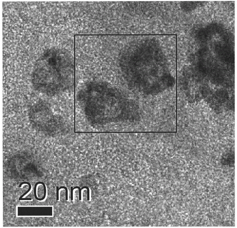
[0025] Embodiment 2: In the fourth step of the preparation process, the alloying temperature is 500° C., and the heat treatment time is 12 hours. Other preparation conditions remained unchanged. The TEM picture of the obtained catalyst is as image 3 shown. image 3 It was shown that the nanoparticles in the catalyst showed a clear hollow structure. image 3 The EDS energy spectrum of the hollow nanoparticles shown in the middle box is as follows Figure 4 shown. From Figure 4 It can be seen that the nanoparticles are composed of two elements, Ni and Au. This shows that the hollow nanoparticles in the catalyst are AuNi alloy.

Embodiment approach 3

[0026] Embodiment 3: In the fourth step of the preparation process, the alloying temperature is 600° C., and the heat treatment time is 12 hours. Other preparation conditions remained unchanged. The TEM picture of the obtained catalyst is as Figure 5 shown. Figure 5 It was shown that the nanoparticles in the catalyst showed a clear hollow structure. Figure 5 The EDS energy spectrum of the hollow nanoparticles shown in the middle box is as follows Figure 6 shown. From Figure 6 It can be seen that the nanoparticles are composed of two elements, Ni and Au. This shows that the hollow nanoparticles in the catalyst are AuNi alloy.

[0027] Embodiment 4: In the fourth step of the preparation process, the alloying temperature is 400° C., and the heat treatment time is 8 hours. Other preparation conditions remained unchanged. The TEM picture of the obtained catalyst is as Figure 7 shown. Figure 7 It was shown that the nanoparticles in the catalyst showed a clear hollow...


PUM


Abstract

The invention discloses a preparation method of a carbon loaded hollow nanogold nickel alloy catalyst for a direct methanol fuel cell. The preparation method comprises the following steps of: preparing a carbon loaded gold-nickel composite nanoparticle by using ethylene glycol coreduction metal gold and a precursor compound of nickel in an alkalic system, carrying out long-time thermal treatment on the carbon loaded gold-nickel composite nanoparticle at a nitrogen atmosphere of 400-600 DEG C to realize the alloying of metallic nickel and gold, and washing and soaking in dilute sulphuric acid to remove redundant unalloyed metallic nickel. The hollow structure and the chemical compositions of metal nanoparticles in the catalyst are characterized through a transmission electron microscope and energy spectrum analysis.

Description

technical field [0001] The invention relates to a method for preparing a nano-gold-nickel alloy catalyst for direct methanol fuel cells with a hollow structure, and belongs to the technical fields of fuel cell materials and electrocatalysts. Background technique [0002] In order to reduce people's dependence on fossil fuels and alleviate global climate change, fuel cells are widely concerned as an important energy source for future use. A fuel cell is a power generation device that directly converts the chemical energy of fuel into electrical energy through electrode reactions. The process does not involve combustion, and the energy conversion efficiency is not limited by the "Carnot cycle". Its energy conversion efficiency is as high as 60%~ 80%, the actual use efficiency is 2 to 3 times that of ordinary internal combustion engines, and the environmental pollution is small and the noise is low. It is known as the preferred clean and efficient power generation technology in...

Claims


Application Information

Patent Timeline
IPC IPC(8): B01J23/89H01M4/92
CPCY02E60/50
Inventor 闫少辉卢利权张世超李育珍高丽丽张卫柯高利珍
Owner TAIYUAN UNIV OF TECH
Learn More