Compressor exhaust pipe and manufacturing method and application of compressor exhaust pipe

A compressor exhaust and manufacturing method technology, applied in the field of compressors, can solve problems such as complex connection structure, secondary melting of solder, and non-environmental protection

Active Publication Date: 2013-04-10
DONGGUAN JINRUI HARDWARE PROD
View PDF10 Cites 15 Cited by
  • Summary
  • Abstract
  • Description
  • Claims
  • Application Information

AI Technical Summary

Problems solved by technology

This leads to the complexity of the connection structure between the copper pipe and the iron pipe. Moreover, since the copper pipe and the iron pipe are socket-type furnace welding (also known as seam welding), during welding, there will be Vibration and cracking are generated, which cannot meet the industry's requirements for the cleanliness of copper pipes. Moreover, when air-conditioning manufacturers re-solder, it is easy to cause secondary melting of the solder, resulting in poor quality. Furthermore, due to the use of solder, it becomes unfriendly to the environment.

Method used


Image

  • Compressor exhaust pipe and manufacturing method and application of compressor exhaust pipe
  • Compressor exhaust pipe and manufacturing method and application of compressor exhaust pipe
  • Compressor exhaust pipe and manufacturing method and application of compressor exhaust pipe

Examples


Embodiment 1

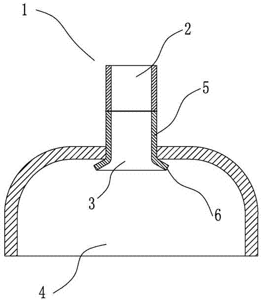
[0036] One of the specific implementations of a compressor discharge pipe of the present invention, such as figure 1 As shown, the compressor exhaust pipe 1 includes a copper pipe section 2 and an iron pipe section 3, the copper pipe section 2 and the iron pipe section 3 are butted, and the two sections are welded together by flash welding between the butt ends to manufacture the compressor exhaust pipe The steps of method 1 are as follows:

[0037] a. Preheating: after the copper pipe section 2 and the iron pipe section 3 of the compressor exhaust pipe 1 are butt-jointed and assembled in the clamp connected to the secondary connection of the welding transformer, a large current is applied to it, according to the calculation formula of Joule heat , by controlling the copper pipe section 2 and the iron pipe section 3 to quickly contact each other to form a closed circuit, and then quickly separate to form an open circuit, so that the resistance R value of the two pairs of ter...

Embodiment 2

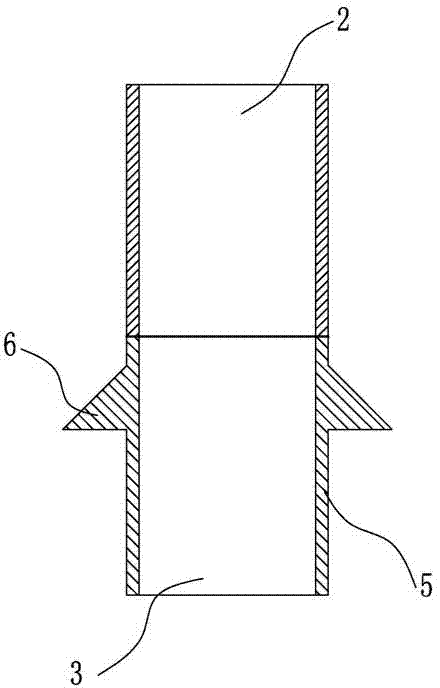
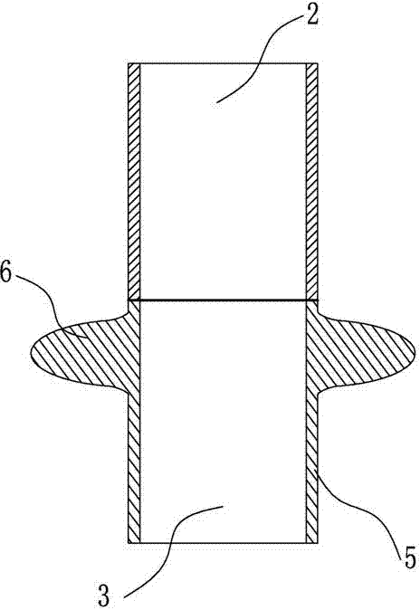
[0044] The second specific embodiment of a compressor discharge pipe of the present invention, as figure 2 , image 3 As shown, the main technical solutions of this embodiment are the same as those of Embodiment 1, and the features not explained in this embodiment are explained in Embodiment 1, and will not be repeated here. The difference between this embodiment and Embodiment 1 is that the welding portion 6 is an annular boss provided on the outer circle of the cylindrical tube portion 5 . Wherein, the annular boss is formed by rotating a convex surface with a triangular cross section around the outer circle of the cylindrical tube part 5 once. Alternatively, the annular boss is an annular boss formed by a semi-elliptical convex surface that rotates around the outer circle of the cylindrical tube part 5 once in cross section. An annular boss is added to facilitate welding.

Embodiment 3

[0046] The third embodiment of a compressor discharge pipe of the present invention is as follows: Figure 4 As shown, the main technical solutions of this embodiment are the same as those of Embodiment 1, and the features not explained in this embodiment are explained in Embodiment 1, and will not be repeated here. The difference between this embodiment and Embodiment 1 is that the welding portion 6 is a flange that is arranged at the bottom end of the cylindrical pipe portion 5 and extends outward, and the outer wall surface of the flange is in contact with the outer surface of the cylindrical pipe portion 5. The walls are arranged at an angle α.

[0047] Preferably, the range of the included angle α is 0°<α<180°.


PUM

PropertyMeasurementUnit
depthaaaaaaaaaa

Abstract

The invention relates to the field of a compressor, in particular to a compressor exhaust pipe and a manufacturing method and application of the compressor exhaust pipe. The compressor exhaust pipe is arranged on an upper cover of the compressor and comprises a copper pipe section and an iron pipe section, the copper pipe section and the iron pipe section are in butt welding through flash welding, and the iron pipe section is connected with the upper cover of the compressor through electric resistance welding. The manufacturing method of the compressor exhaust pipe comprises preheating and upset-forging. The compressor exhaust pipe can be applied to an air conditioning compressor, a refrigerator compressor and a scroll compressor. The connection between the copper pipe section and the iron pipe section of the compressor exhaust pipe and the connection between the iron pipe section and the upper cover of the compressor adopt a welding method without welding materials, the use of the welding materials is completely eradicated, thus the environment cannot be polluted by waste gases such as carbon dioxide generated during a production process, the technology is simplified while the green production is realized, and the manufacturing cost is lowered; and the compressor exhaust pipe has the advantages that the welding quality is good, the welding strength is more reliable, the welding quality is increased, and the service life is prolonged.

Description

technical field [0001] The invention relates to the field of compressors, in particular to a compressor exhaust pipe and its manufacturing method and application. Background technique [0002] The compressor is a fluid machine that raises low-pressure gas to high-pressure gas. It is the heart of the refrigeration system. There is a cylinder inside the shell of the compressor. When working, the low-temperature and low-pressure refrigerant gas enters the cylinder from the intake pipe, and the cylinder After it is compressed, high-temperature and high-pressure refrigerant gas is discharged from the exhaust pipe to provide power for the refrigeration cycle, thereby realizing the refrigeration cycle of compression→condensation→expansion→evaporation. [0003] At present, most of the compressor exhaust pipes in the prior art adopt the structure of a whole copper pipe, which is connected to the upper cover of the compressor through silver solder flame brazing or high-frequency brazi...

Claims


Application Information

Patent Timeline
Patent Type & Authority Applications(China)
IPC IPC(8): F16L13/02B23K11/04
Inventor 陈金龙
Owner DONGGUAN JINRUI HARDWARE PROD
Why Eureka
Try Eureka