System and method for testing catalyst dehydrogenation performance

A technology for testing systems and catalysts, which is applied in the direction of chemical analysis using catalysis, can solve the problems of high container requirements, high energy consumption, and can not meet the performance test of hydrogen elimination catalysts, and achieves the effect of ensuring accuracy and low energy consumption.

Active Publication Date: 2013-04-10
中国船舶集团有限公司第七一八研究所 +1
View PDF11 Cites 12 Cited by
  • Summary
  • Abstract
  • Description
  • Claims
  • Application Information

AI Technical Summary

Problems solved by technology

Therefore, none of the existing experimental devices can meet the performance test of hydrogen elimination catalysts used in nuclear power plants.
In addition, in the prior art, the mixed gas is prepared as the gas source for

Method used


Image

  • System and method for testing catalyst dehydrogenation performance
  • System and method for testing catalyst dehydrogenation performance
  • System and method for testing catalyst dehydrogenation performance

Examples


Embodiment 1

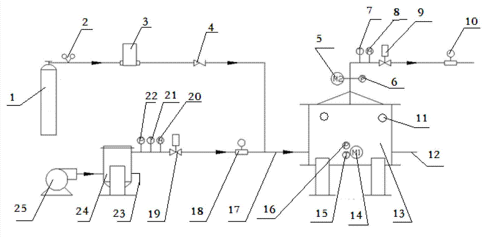
[0063] A test system for catalyst dehydrogenation performance, said system comprising: a hydrogen cylinder 1, a pressure reducing valve 2, a mass flow meter 3, a check valve 4, an air compressor 25, a buffer tank 24, a first electric regulating valve 19, First swirl flowmeter 18, mixing gas distribution pipe 17, catalytic reactor 13, second electric control valve 9, second swirl flowmeter 10, first pressure transmitter 22, first thermocouple 21, first humidity Meter 20, second pressure transmitter 6, second thermocouple 7, second hygrometer 8 and data acquisition control system;

[0064] Among them, the hydrogen cylinder 1, the pressure reducing valve 2, and the mass flow meter 3 are sequentially connected through pipelines, and then connected to one end of the check valve 4;

[0065] The buffer tank 24 bottom has an air inlet, and the upper part has an air outlet; after the air compressor 25, the buffer tank 24 inlet, the buffer tank 24 air outlet, and the first electric regu...

Embodiment 2

[0088] A kind of test system of catalyst dehydrogenation performance, the difference between described system and embodiment 1 is:

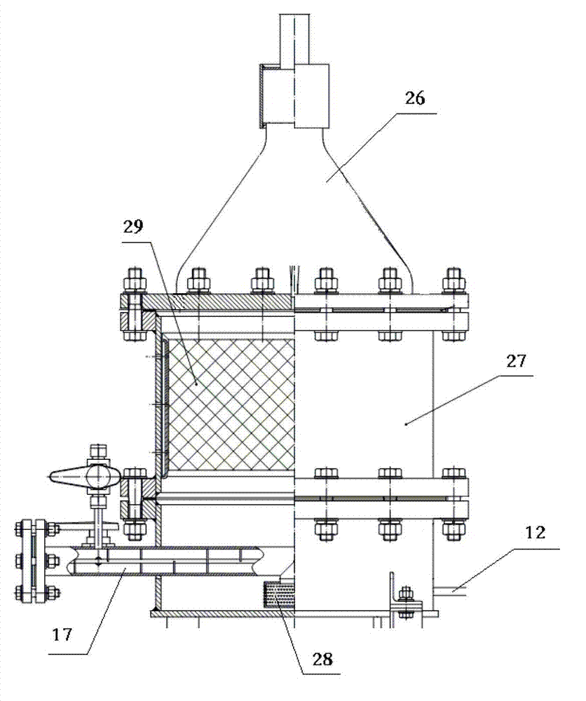
[0089] The lower part of the side wall of the buffer tank 24 has a first liquid filling port 23, and a second liquid filling port 12 is opened below the side wall of the catalytic reactor 13;

[0090] In the catalytic reactor 13, the catalyst plate 29 in the box body 27 is a rectangular box with a grid structure on the surface and a thickness of 6-12 mm, and contains catalyst pellets;

[0091] A method for testing the dehydrogenation performance of a catalyst, the specific steps of the method are as follows:

[0092] Before the test starts, the non-return valve is in the open state, and all other valves are in the closed state;

[0093] Step 1. Open the first electric regulating valve 19, turn on the air compressor 25, fill the buffer tank 24 with compressed air with a pressure of 0.1~0.7MPa, and the air passes through the first electric regulat...


PUM

PropertyMeasurementUnit
Thicknessaaaaaaaaaa
Thicknessaaaaaaaaaa

Abstract

The invention discloses a system and a method for testing the catalyst dehydrogenation performance, and belongs to the field of catalytic reaction engineering. The system comprises a hydrogen gas cylinder, a pressure reducing valve, a mass flowmeter, a check valve, an air compressor, a buffer tank, a first electric control valve, a first vortex precession flowmeter, a mixed gas distribution pipe, a catalytic reactor, a second electric control valve, a second vortex precession flowmeter, a first pressure transmitter, a first thermoelectric couple, a first hygrometer, a second pressure transmitter, a second thermoelectric couple, a second hygrometer and a data acquisition and control system. The method is characterized in that the variation of temperatures, pressures, hydrogen contents and relative humidity at an inlet and an outlet of the catalytic reactor along with time is recorded through the data acquisition and control system. The system and the method, disclosed by the invention, can simulate the design basis accident state of a nuclear power station containment accurately.

Description

technical field [0001] The invention relates to a test system and a test method for the hydrogen elimination performance of a catalyst, belonging to the field of catalytic reaction engineering. Background technique [0002] At present, most of the devices on the market for performance testing of hydrogen elimination catalysts are used for performance testing under high temperature and normal pressure conditions. Most of the catalytic beds used are fixed packed beds in the form of a single circular tube filled with catalyst in the middle. The mixed gas of hydrogen and air (referred to as atmosphere) is introduced from the bottom of the catalytic bed, and discharged from the top after passing through the catalyst filling section. The problem is that the resistance of the air flow passing through the catalyst is large, and the humidity of the atmosphere passing through should not be too high, otherwise it will affect the normal use of the hydrogen analyzer. The hydrogen elimin...

Claims


Application Information

Patent Timeline
IPC IPC(8): G01N31/10
Inventor 姜韶堃赵宁陶智勇朱敏
Owner 中国船舶集团有限公司第七一八研究所
Why Eureka
Try Eureka