Ultrasonic vibration atomizer

A technology of ultrasonic vibration and atomizer, applied in the direction of spraying device, liquid spraying device, etc., can solve the problems of uneven droplet diameter, large atomized particle diameter, low atomization efficiency, etc., and achieve adjustable atomization volume , large power capacity and simple structure

Inactive Publication Date: 2013-04-24
SUZHOU UNIV OF SCI & TECH
View PDF5 Cites 24 Cited by
  • Summary
  • Abstract
  • Description
  • Claims
  • Application Information

AI Technical Summary

Problems solved by technology

[0008] Common mechanical atomization and ultrasonic atomization methods have problems such as complex structure, high cost, high power consumption, large atomized particle diameter, low atomization efficiency, and small atomization flow rate. In order to meet the needs of new industrial applications, the development Green and efficient atomization technology has become one of the foundations and key technologies for the development of new industrial technologies. While ensuring excellent atomization effects, improving atomization efficiency and atomization quality, it minimizes power consumption and reduces environmental pollution. , to achieve green and low-carbon production, easier to control and more environmentally friendly
[0009] In order to overcome the shortcomings of the above atomization technology, the patent document with the publication number CN102500502A discloses a two-stage ultrasonic vibration atomizer, which adopts a sandwich transducer structure, has a large power capacity, and can atomize The advantage of strong ability, but the ultrasonic atomizer also has some defects. The inclined micro-holes of the primary atomizing nozzle of the atomizer are difficult to manufacture and install. To reduce the droplet diameter, the vibration frequency of the system needs to be increased, which further increases the It is difficult to manufacture, and the diameter of the atomized droplets on the secondary atomization surface is not uniform enough. Although the atomization effect is improved compared with the general ultrasonic vibration atomizer, the problem of uneven droplet diameter has not been fundamentally solved.

Method used


Image

  • Ultrasonic vibration atomizer
  • Ultrasonic vibration atomizer
  • Ultrasonic vibration atomizer

Examples


Embodiment 1

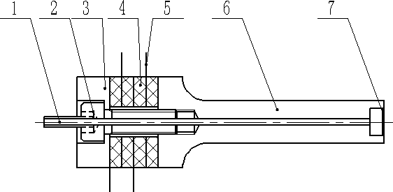
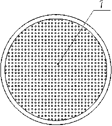
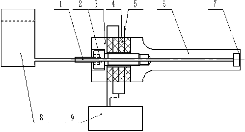
[0033] like image 3 As shown, the embodiment of the present invention adopts piezoelectric ceramic sandwich structure, including liquid delivery pipe (1), bolt (2), rear cover plate (3), electrode sheet (4), piezoelectric ceramic sheet (5) , the horn (6) and the mesh vibrating plate (7), the rear cover (3), the electrode sheet (4), the piezoelectric ceramic sheet (5) and the variable The rod (6) is sequentially sleeved on the bolt (2), the rear cover (3), the electrode sheet (4), the piezoelectric ceramic sheet (5) and the The horn (6) is connected and clamped by the bolt (2), the liquid delivery pipe (1) is connected to the rear end of the bolt (2), and the mesh vibrating plate (7) is set on The front end of the horn (6). The liquid delivery pipeline (1) is connected with a certain amount of liquid supply device (8). The electrode sheet of the ultrasonic vibrating nebulizer is connected with an ultrasonic power supply (9).

[0034] The piezoelectric ceramic transducer se...


PUM


Abstract

The invention discloses an ultrasonic vibration atomizer which comprises a liquid delivery pipeline, a bolt, a rear cover plate, a piezoelectric ceramic wafer, an electrode piece, an amplitude changing rod and a mesh vibration plate. The rear cover plate, the piezoelectric ceramic wafer, the electrode piece and the amplitude changing rod are sequentially sleeved on the bolt and connected and clamped through the bolt, the liquid delivery pipeline is connected at the rear end of the bolt, and the mesh vibration plate is arranged at the front end of the amplitude changing rod. An energy converter is of a sandwich type structure, and the ultrasonic vibration atomizer has the advantages of large power capacity, tiny and uniform in fogdrop after atomizing, effective in liquid medium atomizing, easy to control atomizing amount and the like.

Description

technical field [0001] The invention relates to the field of ultrasonic vibration atomization utilizing the piezoelectric effect, in particular to an ultrasonic vibration atomizer. [0002] Background technique [0003] In many fields such as cooling, air humidification, medical treatment, dust removal, deodorization, textile, printing and dyeing, tobacco, flowers, telecommunications, papermaking, electronics, landscape, spraying, steel, chemical industry, cleaning, granulation, fungus cultivation, fruit storage, etc. Both need to atomize the liquid medium, and the commonly used atomization methods are as follows: [0004] (1) Mechanical atomization [0005] Pressurize the liquid, and inject it into the static or low-speed airflow from the nozzle at high speed and high pressure, and the injection speed increases; when the liquid is ejected, due to the sudden decrease in pressure, the liquid will drop by the joint action of surface tension, viscosity and air resistance. , ...

Claims


Application Information

Patent Timeline
Patent Type & Authority Applications(China)
IPC IPC(8): B05B17/06
CPCB05B17/063B05B17/0638
Inventor 李华殷振曹自洋谢鸥汪帮富赵江江任坤张峰李艳李征
Owner SUZHOU UNIV OF SCI & TECH
Why Eureka
Try Eureka