Powdery material suspension type heat exchanger device and powdery material heat exchanger system

A powdery material and heat exchange device technology, which is applied in the direction of preheating costs, lighting and heating equipment, furnace cooling, etc., to achieve the effect of reducing building height, low temperature, and good sulfur fixation effect

Inactive Publication Date: 2013-05-15
刘红锁 +2
View PDF7 Cites 2 Cited by
  • Summary
  • Abstract
  • Description
  • Claims
  • Application Information

AI Technical Summary

Problems solved by technology

[0005] The technical problem to be solved by the present invention is to improve the existing problems of various preheater systems, to provide a kind of flexible structure layout, simple construction, low cost, small pressure loss, low power consumption, high heat exchange efficiency, Powder material suspension heat exchange device and powder material heat exchange system with good separation effect and less harmful exhaust gas emission

Method used


Image

  • Powdery material suspension type heat exchanger device and powdery material heat exchanger system
  • Powdery material suspension type heat exchanger device and powdery material heat exchanger system

Examples


Embodiment 1

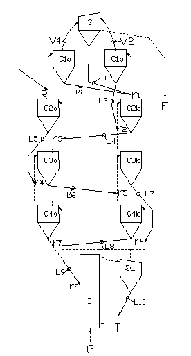
[0018] figure 1 An embodiment of the raw meal heat exchange device used in cement production equipment of the present invention, that is, the preheater system is given. The multiple cyclone heat exchangers of the preheater system are arranged in 2 rows and 4 stages, and 1-4 stages Two cyclone heat exchangers respectively, C1a, C1b and C2a, C2b and C3a, C3b and C4a, C4b.

[0019] Airflow Routes: The airflow routes are shown in dashed lines with arrows in the attached drawings. Such as figure 1 As shown, the kiln gas enters the general air inlet chamber (in this embodiment, the decomposition furnace D), and the insufficient heat source can be supplemented by supplementing the heat source T. The gas after the decomposition furnace enters the cyclone heat exchange collector Sc, and the Sc exits The tuyere is connected to the C4a and C4b air inlets in two ways, and then enters the C4a-C3a-C2a-C1a column and the C4b-C3b-C2b-C1b column respectively, and finally merges into the cycl...

Embodiment 2

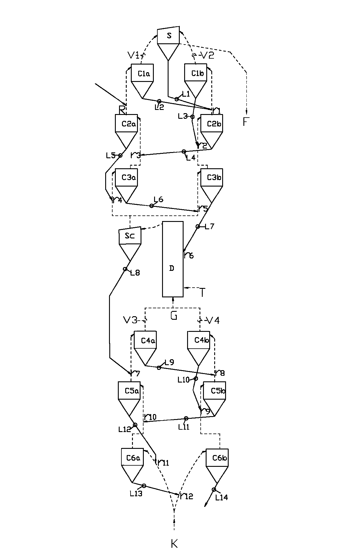
[0022] figure 2 A powder material heat exchange system including two powder material suspension heat exchange devices is given. Specifically, it is an embodiment of a calcined lime production process, in which the two powdery material suspension heat exchange devices are respectively a heating reaction device for raw meal and a cooling device for high-temperature lime products. The system recycles the waste heat of high-temperature lime products, and also saves the lime kiln compared with the traditional system.

[0023] Airflow route: eg figure 2 As shown, the air K enters the air inlet pipes of cyclone heat exchangers C6a and C6b in two ways, and enters the cooling device, and the air flow passes through C6a, C5a, C4a and C6b, C5b, C4b cyclone heat exchangers to cool the high-temperature lime respectively. , the high-temperature gas generated by cooling the lime flows into the calciner D to decompose the limestone powder through the C4a and C4b outlet pipes, and the insu...


PUM


Abstract

The invention relates to a powdery material suspension type heat exchanger device and a powdery material heat exchange system. The device comprises at least two rows of cyclone heat exchangers in parallel, wherein each row of cyclone heat exchangers includes at least two stages of heat exchangers; gas flow flows according to follow paths: the gas flow paths among all the row of cyclone heat exchangers are connected in parallel, and the gas flow paths of each row of cyclone heat exchangers are connected in series; powdery material flow flows according to the following material flow path: the material flow paths of each stage of heat exchangers are connected in series; and the two adjacent stages of cyclone heat exchangers adopt the following material flow connecting ways: a former-stage cyclone heat exchanger located at the terminal end of the material flow series connection path is directly connected with a later-stage cyclone heat exchanger (in the same row of the former-stage cyclone heat exchanger) in a way of former-later stage series connection; and the cyclone heat exchanger in the later-stage in the same row is located at the initial end of the later stage of cyclone heat exchangers. The powdery material heat exchange device and system are flexible in structural arrangement, simple in construction, cost-saving, small in pressure loss, low in power consumption, high in heat exchange efficiency, and good in separating effect, and the harmful exhaust emission amount is small.

Description

technical field [0001] The invention belongs to the field of gas-solid phase heat exchange or heat reaction, in particular to a powder material suspension heat exchange device capable of exchanging, reacting and separating powder materials in a suspended state in cement and other production fields and a powder Material heat exchange system. Background technique [0002] Since the Czech engineer M.Voel-Jorgensen submitted the patent for heating cement raw meal powder in a single-row suspension preheater composed of multiple cyclone heat exchangers in series in 1932, the cement production quality has been greatly improved, and the heat consumption has also been significantly reduced. However, the exhaust temperature of the first-stage air outlet pipe is still relatively high. Taking the third-stage and fourth-stage single-row preheaters as an example, it reaches 310-400°C; some people increase the number of stages in order to reduce heat energy loss and improve thermal efficie...

Claims


Application Information

Patent Timeline
Patent Type & Authority Applications(China)
IPC IPC(8): F27D13/00F27D9/00
Inventor 刘红锁刘政钱慧王西军牛华军
Owner 刘红锁
Why Eureka
Try Eureka