Pulse pump type standing wave resonant cavity nanosecond pulse laser

A pump laser, nanosecond pulse technology, applied in the field of lasers, can solve the problems of pulse asymmetry, limited duty cycle, burnt gain fiber, etc., to overcome large insertion loss, reduced circuit complexity, and optical-to-optical conversion efficiency. high effect

Inactive Publication Date: 2013-06-12
广东华快光子科技有限公司
View PDF3 Cites 9 Cited by
  • Summary
  • Abstract
  • Description
  • Claims
  • Application Information

AI Technical Summary

Problems solved by technology

The laser pulse width output by the acousto-optic Q-switched laser is about 100-300ns. Moreover, the acousto-optic switch has poor switching capability for high-energy lasers, and its time-domain waveform has a long falling edge time and pulse asymmetry, which is limited by the switching time of the Q-switched crystal. limit, it is not possible to obtain nanosecond pulses with steep rising edges
[0004] The semiconductor seed source technology with direct modulation and fast response has a large repetition frequency tuning range, and the pulse waveform is easy to control. However, when working at a low repetition frequency, it is limited by the duty cycle and the average power is very small, only hundreds of microwatts. Generally, it needs Multi-level amplification can meet the needs of industrial processing
Moreover, the spectral width of the pulse directly output from the semiconductor seed source is only 0.2-0.4nm, such a narrow spectral width is very easy to stimulate various nonlinear effects in the subsequent multi-stage amplification process, such as SBS stimulated Brillouin scattering , Stimulated Raman scattering effect, etc., causing pulse spectrum distortion, time domain distortion, and even burning the gain fiber in severe cases

Method used


Image

  • Pulse pump type standing wave resonant cavity nanosecond pulse laser
  • Pulse pump type standing wave resonant cavity nanosecond pulse laser
  • Pulse pump type standing wave resonant cavity nanosecond pulse laser

Examples


Embodiment 1

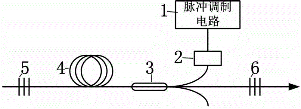
[0027] Such as figure 1 As shown, a pulse-pumped standing wave resonator nanosecond pulse laser includes a pulse modulation circuit 1, a pump laser 2, a combiner 3, a gain fiber 4, a high reflection fiber grating 5 and a low reflection fiber grating 6 , The beam combiner 3 is provided with a beam combining end, a pump light input end and a signal input end, the output end of the pump laser 2 is connected with the pump light input end of the beam combiner 3, and the high reflection One end of the fiber grating 5 is connected to one end of the gain fiber 4, the other end of the gain fiber 4 is connected to the combining end of the combiner 3, and the signal incident end of the combiner 3 is connected to one end of the low reflection fiber grating 6 to form a standing wave for laser resonance Cavity, the other end of the low reflection fiber grating 6 is used as a nanosecond pulse output end.

[0028] In this embodiment, the pump laser 2 uses a semiconductor laser with a continuous ...

Embodiment 2

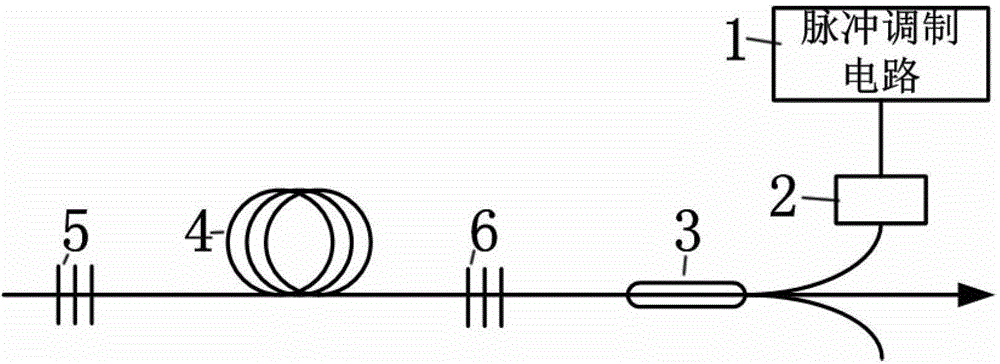
[0035] Such as figure 2 As shown, a pulse-pumped standing wave resonator nanosecond pulse laser includes a pulse modulation circuit 1, a pump laser 2, a combiner 3, a gain fiber 4, a high reflection fiber grating 5 and a low reflection fiber grating 6 , The beam combiner 3 is provided with a beam combining end, a pump light input end and a signal input end, the output end of the pump laser 2 is connected with the pump light input end of the beam combiner 3, and the high reflection One end of the fiber grating 5 is connected to one end of the gain fiber 4, the other end of the gain fiber 4 is connected to one end of the low reflection fiber grating 6 to form a standing wave harmonic cavity, and the other end of the low reflection fiber grating 6 is connected to the beam combining end of the combiner 3, The nanosecond pulse is output through the signal incident end of the beam combiner 3.

[0036] In this embodiment, the pump laser 2 is a semiconductor laser with a continuous opti...

Embodiment 3

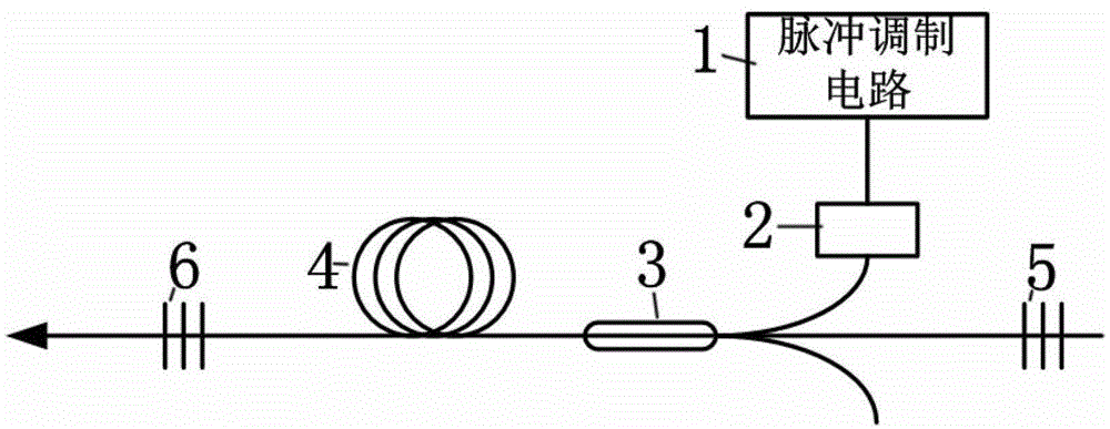
[0043] Such as image 3 As shown, a pulse-pumped standing wave resonator nanosecond pulse laser includes a pulse modulation circuit 1, a pump laser 2, a combiner 3, a gain fiber 4, a high reflection fiber grating 5 and a low reflection fiber grating 6 , The beam combiner 3 is provided with a beam combining end, a pump light input end and a signal input end, the output end of the pump laser 2 is connected with the pump light input end of the beam combiner 3, and the high reflection One end of the fiber grating 5 is connected to the signal incident end of the beam combiner 3, the combining end of the beam combiner 3 is connected to one end of the gain fiber 4, and the other end of the gain fiber 4 is connected to one end of the low reflection fiber grating 6 to form a standing wave resonant cavity. The other end of the low reflection fiber grating 6 is used as a nanosecond pulse output end.

[0044] In this embodiment, the pump laser 2 is a semiconductor laser with a continuous opt...


PUM


Abstract

The invention discloses a pulse pump type standing wave resonant cavity nanosecond pulse laser which comprises a pulse modulation circuit, a pump laser, a beam combiner, a gain fiber, an isolator and an output coupler; a doped fiber in a resonant cavity not only can play a role in gaining a medium under the pulse pump condition, but also can be taken as a saturable switch for quick response to generate a laser pulse of which the time domain width is within the nanosecond order of magnitude; the repetition frequency of the pulse depends on that of pump light; and the pulse width depends on the combined action of energy in the cavity and the length of the resonant cavity. The pulse pump type standing wave resonant cavity nanosecond pulse laser has the advantages of simple structure, tunable pulse width, tunable repetition frequency, high optical to optical conversion efficiency and the like, has good stability and is suitable for various application occasions for industrial processing.

Description

[Technical Field] [0001] The invention relates to the field of lasers, in particular to a pulse pumped standing wave resonator nanosecond pulse laser. [Background technique] [0002] With the widespread use of laser cutting, laser engraving, laser marking, laser scribing and other technologies in the fields of clothing, electronics, microprocessing, etc., the demand for nanosecond pulses with high stability, pulse width and repetition frequency tunable is also increasing. More urgent. At present, the commonly used methods for generating nanosecond pulses in the industrial processing field mainly fall into two categories: acousto-optic Q-switching technology and direct modulation and fast response semiconductor seed source technology. [0003] Acousto-optic Q-switching technology actually adds two coupling fibers on the basis of the bulk acousto-optic Q-switch. Due to the technology level of coupling the pigtail and the acousto-optic Q crystal, the insertion loss of the entire Q sw...

Claims


Application Information

Patent Timeline
Patent Type & Authority Applications(China)
IPC IPC(8): H01S3/067H01S3/08H01S3/11
Inventor 梁崇智曾和平杨康文
Owner 广东华快光子科技有限公司
Why Eureka
Try Eureka