Shutdown technique of cleaner production of sulfur recovery and tail gas treatment device

A technology for tail gas treatment and clean production, applied in the preparation/purification of sulfur, etc., can solve the problems of difficult fuel gas combustion control, environmental pollution, system flying temperature, etc., to improve the controllability of the device, low cost, The effect of reducing operating costs and energy consumption

Active Publication Date: 2013-06-19
SHANDONG SUNWAY PETROCHEMICAL ENGINEERING CO LTD
View PDF8 Cites 10 Cited by
  • Summary
  • Abstract
  • Description
  • Claims
  • Application Information

AI Technical Summary

Problems solved by technology

There are great risks in the above operations. On the one hand, due to the difficulty in controlling the combustion of fuel gas, once overoxygen occurs during the sulfur blowing operation, it is easy to cause the system to overheat and burn the equipment; on the other hand, the passivation A large amount of sulfur dioxide (formed by the reaction of oxygen and ferrous sulfide) will inevitably be produced during the operation, which will seriously pollute the environment

Method used


Image

  • Shutdown technique of cleaner production of sulfur recovery and tail gas treatment device

Examples


Embodiment 1

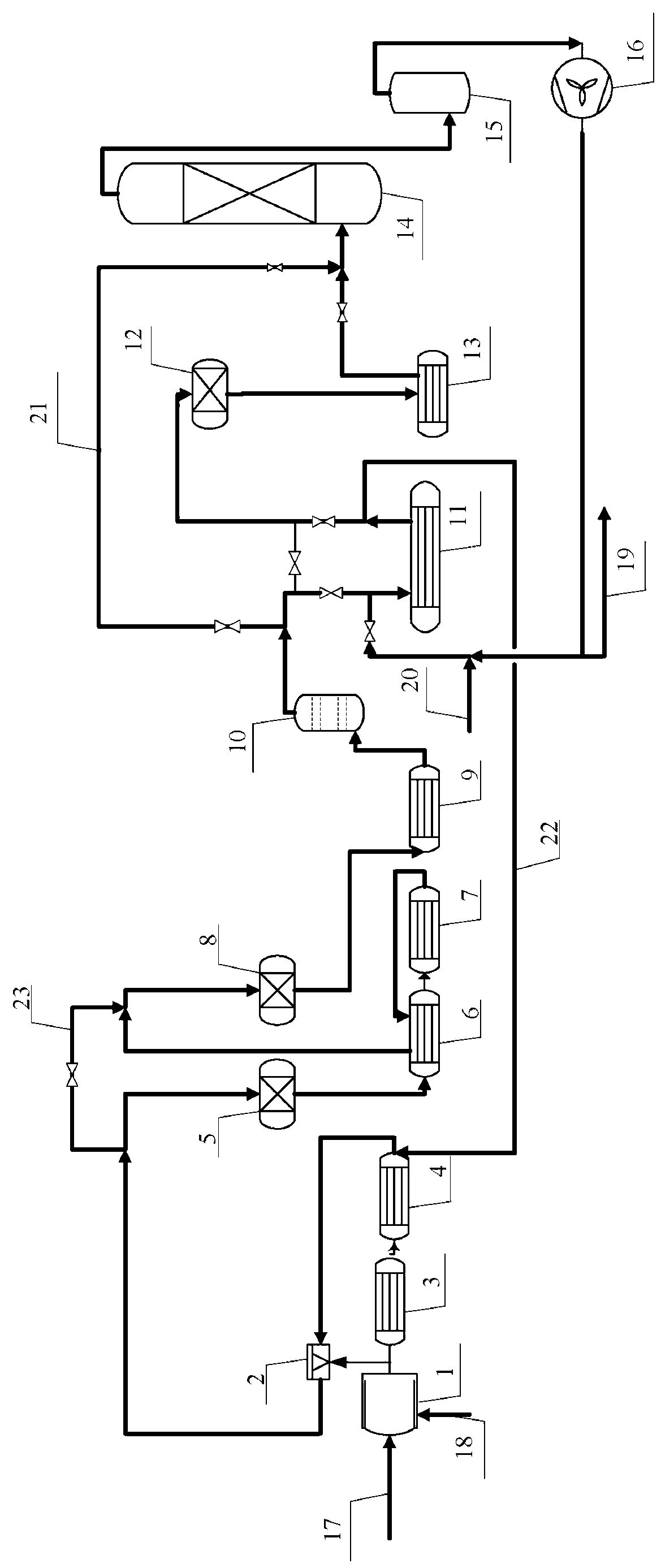
[0049] (1) Sulfur blowing operation of sulfur recovery unit:

[0050] Nitrogen is pressurized by the exhaust fan into the exhaust heater to be heated to 320℃, 80% of the heated nitrogen enters the primary sulfur reactor for sulfur blowing operation, then the gas enters the process gas heat exchanger tube side to cool to 260℃, and then enters In the secondary sulfur cooler, sulfur mist is condensed from the liquid sulfur outlet and enters the sulfur sealing tank; the circulating nitrogen temperature at the outlet of the secondary sulfur cooler drops to 160℃, and enters the process gas heat exchanger shell side and tube side for gas exchange After heating, the temperature is increased to 222℃, and then mixed with the remaining 20% ​​of the heated nitrogen from the tail gas heater, the temperature reaches 260℃ and enters the secondary sulfur reactor for sulfur blowing operation. After the sulfur is blown, the gas enters the tertiary sulfur cooler , The temperature drops to 160℃, the...

Embodiment 2

[0057] (1) Sulfur blowing operation of sulfur recovery unit:

[0058] Nitrogen is pressurized by the exhaust fan into the exhaust heater to be heated to 310℃, 80% of the heated nitrogen enters the primary sulfur reactor for sulfur blowing operation, and then the gas enters the process gas heat exchanger tube side to cool to 247℃, and then enters In the secondary sulfur cooler, the sulfur mist is condensed from the liquid sulfur outlet and enters the sulfur sealing tank; the circulating nitrogen temperature at the outlet of the secondary sulfur cooler drops to 155℃, and enters the process gas heat exchanger shell side and tube side for gas exchange After heating, the temperature is increased to 212°C, and then mixed with the remaining 20% ​​of the heated nitrogen from the tail gas heater. The temperature reaches 250°C and enters the secondary sulfur reactor for sulfur blowing. After the sulfur is blown, the gas enters the tertiary sulfur cooler , The temperature drops to 155℃, the...

Embodiment 3

[0065] (1) Sulfur blowing operation of sulfur recovery unit:

[0066] Nitrogen is pressurized by the exhaust fan into the exhaust heater to be heated to 300°C, 80% of the heated nitrogen enters the primary sulfur reactor for sulfur blowing operation, and then the gas enters the process gas heat exchanger tube to cool down to 240°C, and then enters In the secondary sulfur cooler, the sulfur mist is condensed from the liquid sulfur outlet and enters the sulfur sealing tank; the circulating nitrogen temperature at the outlet of the secondary sulfur cooler drops to 150℃, and enters the process gas heat exchanger shell side and tube side for gas exchange After heating, the temperature is raised to 210°C, and then mixed with the remaining 20% ​​heated nitrogen from the tail gas heater. The temperature reaches 240°C and enters the secondary sulfur reactor for sulfur blowing. After the sulfur is blown, the gas enters the tertiary sulfur cooler , The temperature drops to 150℃, the sulfur ...


PUM


Abstract

The invention belongs to the technical field of sulfur recovery, and particularly relates to a sulfur recovery and tail gas liquid phase treatment technique. The technique comprises the following steps: heating circulating nitrogen and purging a sulfur recovery unit to generate sulfur-mist-containing gas; directly contacting the sulfur-mist-containing gas with water for cooling, and condensing the sulfur mist to form sulfur powder and removing the sulfur powder for gaseous phase circulation; heating by using the circulating nitrogen containing trace O2 to forge the sulfur recovery and tail gas treatment device to generate SO2-containing gas; and directly contacting the SO2-containing gas with NaOH dilute solution for cooling, and entering the produced industrial wastewater into a sludge treatment device. According to the technique, the shutdown device is treated by using high-temperature nitrogen in place of smoke gas generated from combustion of fuel gas, so that the controllability of the device is greatly improved, the service lives of the equipment and catalyst can be effectively prolonged, the discharge of sulfur dioxide in the shutdown period of the sulfur recovery device is less than 10ppm, and the environmental pollution is greatly reduced.

Description

Technical field [0001] The invention belongs to the technical field of sulfur recovery, and specifically relates to a process for ensuring no emissions during the startup and shutdown of a sulfur recovery and tail gas treatment device. Background technique [0002] The shutdown process of the sulfur recovery device requires multiple processes to process the system. First, the material of the sulfur recovery device needs to be switched to fuel gas. The heat generated by the equivalent combustion of the fuel gas is used to maintain the heat balance of the sulfur recovery device and the fuel gas is burned to generate The flue gas purges the remaining liquid sulfur in the entire system, and purges the liquid sulfur to a low point as a product recovery, referred to as sulfur blowing operation; after the remaining sulfur in the system is recovered, it is necessary to gradually increase the oxygen content in the flue gas. Gradually oxidize the remaining ferrous sulfide in the system to ...

Claims


Application Information

Patent Timeline
Patent Type & Authority Applications(China)
IPC IPC(8): C01B17/02
Inventor 李铁军
Owner SHANDONG SUNWAY PETROCHEMICAL ENGINEERING CO LTD
Why Eureka
Try Eureka