

Copper foil production conjoint machine and high-bonding strength copper foil technology for lithium ion battery
A conjoined machine, high bonding technology, applied in electroforming, electrolysis process, etc., can solve problems such as poor bonding force, and achieve the effect of reducing emissions, easy operation and environmental protection
- Summary
- Abstract
- Description
- Claims
- Application Information
AI Technical Summary
Problems solved by technology
Method used
Image

Examples
Embodiment 1
[0050] Integrated processor for copper foil production, see Figure 4 and Figure 5 , including a raw foil machine 5 and a post-processing machine 6, the raw foil machine includes a cathode roll 5-1, an arc-shaped anode tank 5-2, the cathode roll is rotated in the anode tank, and the post-processing machine is sequentially connected to include copper foil Pretreatment tank 6-1, first washing tank 6-2, passivation tank 6-3, second washing tank 6-4 and winding device 6-5; wherein, the post-processing machine is connected after the foil machine , the straight-line distance between the copper foil input roller 7 in the pretreatment tank of the post-processing machine and the copper foil stripping roller 8 of the raw foil machine is not more than 3 meters, and the two faces of the copper foil 9 in the pretreatment tank along the direction of entering the tank are respectively set There are anode plates 10 for roughening treatment, and at the same time, anode plates 11 for curing t...
Embodiment 2
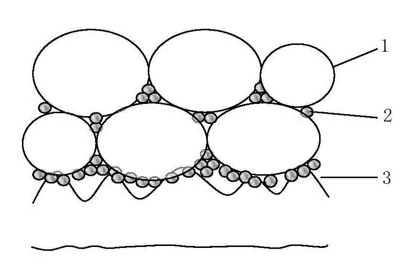
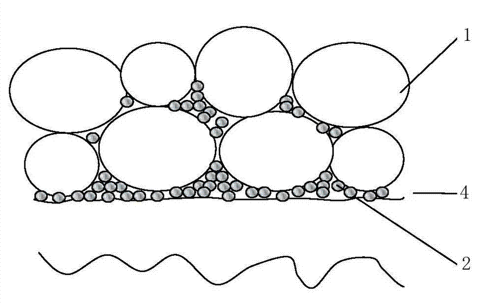
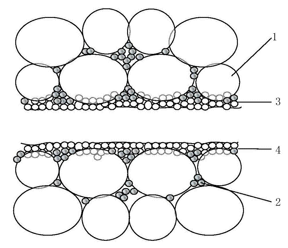
[0054] Lithium-ion battery high bond strength copper foil process, this process is based on the post-treatment process of the lithium-ion battery high bond strength copper foil produced by the copper foil in embodiment 1. The content of the post-processor in embodiment 1 should be As the content of the post-processing machine in this embodiment, the post-processing process includes feeding the copper foil with the double-sided roughness Rz less than 1.7 microns and Ra less than 0.25 microns from the peeling roller of the raw foil machine into the copper foil through the copper foil introduction roller. The post-processing machine performs double-sided roughening treatment, double-sided curing treatment, water washing, double-sided passivation treatment and water washing, wherein the double-sided roughening treatment and double-sided curing treatment are both in the pretreatment tank of the post-processing machine In the pretreatment tank, the two sides of the copper foil along ...
Embodiment 3
[0062] Since the usual anti-oxidation passivation treatment is chromium-containing anti-oxidation passivation treatment, because chromium is a carcinogen, no matter it is acidic or alkaline chromic acid solution, it cannot meet the requirements of environmental protection. Chromium-containing products are prohibited from being imported in the European Union (RoHS) and the United States. It has also been included in the zero discharge wastewater standard in China. Therefore, the present embodiment is a further optimized scheme based on embodiment 2, the solution of the passivation treatment is deionized water as the basic solvent, and its process parameters are:
[0063] Sodium stannate 6-20 g / l
[0064] Sodium hydroxide 8 g / l
[0065] Temperature 30-60℃
[0066] Current density 0.5 – 1.5 A / dm 2 ,
[0067] The electrodeposition thickness is less than 0.5 microns.
[0068] Among them, sodium stannate is a standard chemical product in the market.
PUM
| Property | Measurement | Unit |
|---|---|---|
| Diameter | aaaaa | aaaaa |
Abstract
Description
Claims
Application Information