Cutting tool for improving coating structure, and preparation method thereof

A cutting tool and coating technology, applied in the field of cutting tools and their preparation processes, can solve the problems of non-densification, reducing the strength of the surface α-Al coating, and the grain growth of the transition layer, so as to avoid the coating strength and coating. The effect of reducing layer bonding strength, improving nucleation uniformity and density, and avoiding the decrease in grain density

Active Publication Date: 2013-06-26
ZHUZHOU CEMENTED CARBIDE CUTTING TOOLS CO LTD
View PDF21 Cites 27 Cited by
  • Summary
  • Abstract
  • Description
  • Claims
  • Application Information

AI Technical Summary

Problems solved by technology

[0006] However, due to the needle-like structure of TiCO, TiAlCNO, TiBN and other oxygen-containing coatings, they are brittle and have limited effects on the diffusion of cobalt and tungsten from the substrate to the coating when the thickness is thin; and a single TiO, TiCO Or the TiAlCO transition layer cannot nucleate uniformly on the surface of the bottom coating A, so when the deposition time is short, the distribution of the TiCO transition layer on the bottom coating A is uneven and not dense, further affecting the outer layer α-Al 2 o 3 The nucleation of the outer oxide layer leads to coarse grains and inhomogeneity of the coating; while the thickness of the oxygen-containing transition layer is too thick, it will lead to the growth of tra

Method used


Image

  • Cutting tool for improving coating structure, and preparation method thereof
  • Cutting tool for improving coating structure, and preparation method thereof
  • Cutting tool for improving coating structure, and preparation method thereof

Examples


Embodiment 1

[0056] a kind of like figure 1 The cutting tool with improved coating structure of the present invention shown includes a substrate 1 and a coating 2 at least partially covered on the substrate 1. The coating 2 includes at least an inner layer A21, a transition layer C22 and an outer layer from the inside to the outside. Layer B 23;

[0057] The inner layer A21 is mainly composed of TiCN material with a thickness of 6 μm;

[0058] The outer layer B 23 is mainly composed of α-Al 2 o 3 Composition of materials, thickness d=4 μm, outer layer B 23 is an oxide coating with ultra-fine grains, and the average grain size S of outer layer B is 0.46 μm;

[0059] Transition layer C 22 includes transition layer C1 221, transition layer C2 222 and transition layer C3 223 from outside to inside:

[0060] The transition layer C1 221 is mainly composed of titanium carbonitride TiC x1 N y1 o z1 Composition (specifically TiC 0.5 o 0.5 ), x1, y1, z1 represent TiC x1 N y1 o z1 The atomi...

Embodiment 2

[0076] a kind of like figure 1 The cutting tool with improved coating structure of the present invention shown has the same coating structure, composition, microscopic composition, etc. as the cutting tool in Example 1, except for the coating thickness of the transition layer C3 and the outer layer α -Al 2 o 3 The average grain size is slightly different from Example 1. In this embodiment, the coating thickness of the transition layer C3 is 0.2 μm, and the average grain size S of the outer layer B is 0.5 μm. The main coating structures of the cutting tools in Example 1 and Example 2 are shown in Table 2 below. The preparation method of this embodiment 2 is basically the same as that of embodiment 1.

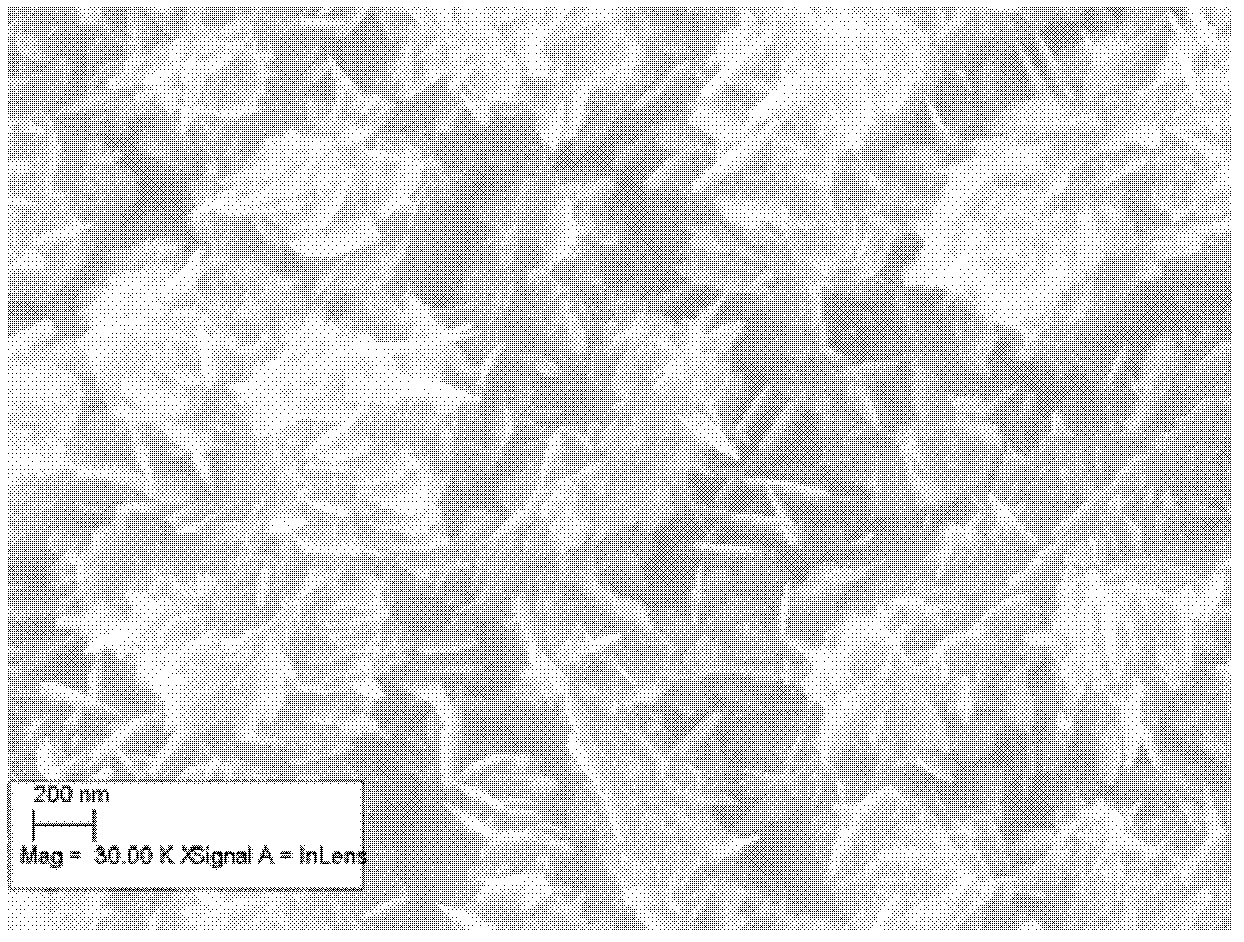
[0077] Two kinds of comparative cutting tool 1 (comparative example 1) and comparative cutting tool 2 (comparative example 2) are selected in addition, and its main coating structure is shown in the following table 2, wherein the surface microstructure of outer layer B and tr...

Embodiment 3

[0090] a kind of like figure 1 The cutting tool with improved coating structure of the present invention shown includes a substrate 1 and a coating 2 at least partially covered on the substrate 1. The coating 2 includes at least an inner layer A21, a transition layer C22 and an outer layer from the inside to the outside. Layer B 23;

[0091] The inner layer A21 is mainly composed of MT-TiCN material with a thickness of 4 μm;

[0092] The outer layer B 23 is mainly composed of α-Al 2 o 3 Composed of materials, the thickness is d=3 μm, the outer layer B 23 is an oxide coating with ultrafine grains, and the average grain size S of the outer layer B is 0.51 μm;

[0093] Transition layer C 22 includes transition layer C1 221, transition layer C2 222 and transition layer C3 223 from outside to inside:

[0094] The transition layer C1 221 is mainly composed of titanium carbonitride TiC x1 N y1 o z1 Composition (specifically TiC 0.3 o 0.7 ), namely x1=0.3, y1=0, z1=0.7, z1 / (x...


PUM

PropertyMeasurementUnit
Thicknessaaaaaaaaaa
Thicknessaaaaaaaaaa
Thicknessaaaaaaaaaa

Abstract

The invention discloses a cutting tool for improving a coating structure. The cutting tool comprises a base body and a coating arranged on the base body, wherein the coating comprises an inner layer A, a transition layer C and an outer layer B from inside to outside; the inner layer A mainly comprises compound material formed by transition elements and non-metallic elements; the outer layer B mainly comprises oxide and the like; the transition layer C comprises a transition layer C1, a transition layer C2 and a transition layer C3 from outside to inside; the transition layer C1 mainly consists of TiCx1Ny1Oz1; the transition layer C2 mainly consists of TiCx2Ny2Oz2; and the transition layer C3 mainly consists of TiAlCx3Ny3Oz3 or TiCx3Ny3Oz3. A preparation method of the cutting tool comprises the steps of: combining chemical vapor deposition (CVD) and high-temperature (HT)-CVD onto the base body, and coating in sequence by various coating technologies. The cutting tool has the advantages of being good in wear resistance, high in adhesive force, high in inhibition, etc.

Description

technical field [0001] The invention belongs to the field of metal cutting, in particular to a coated cutting tool and a preparation process thereof. Background technique [0002] Coated cutting tool inserts are widely used in machining in various industries such as automobiles, aviation, and microelectronics. The processing materials include ordinary metal materials such as steel, copper, and aluminum, as well as various alloys, ceramics, or composite materials. In the machining process, there are two failure systems for coated tools: wear and damage. Tool wear is mainly abrasive wear, adhesive wear, diffusion wear, and oxidation wear. Under different cutting conditions, when processing workpieces of different materials, the main reason for wear may be one or two of them. Generally speaking, when the cutting temperature is low, it is mainly abrasive wear, and when the cutting temperature is high, it is mainly due to diffusion wear. , mainly oxidative wear. [0003] Now i...

Claims


Application Information

Patent Timeline
IPC IPC(8): B32B9/04
Inventor 王社权刘王平陈响明李秀萍
Owner ZHUZHOU CEMENTED CARBIDE CUTTING TOOLS CO LTD
Why Eureka
Try Eureka