Fiber grating wavelength synchronous demodulation system with distance measurement function

A technology of optical fiber grating and synchronous demodulation, which is applied in the direction of light demodulation, optics, and the use of optical devices to transmit sensing components, etc. Difficult to accurately measure the transmission distance and other issues

Active Publication Date: 2013-07-03
SHANGHAI BAIANTEK SENSING TECH CO LTD
View PDF7 Cites 10 Cited by
  • Summary
  • Abstract
  • Description
  • Claims
  • Application Information

AI Technical Summary

Problems solved by technology

[0014] In the wavelength demodulation equipment designed based on the wavelength tunable filtering method, the wavelength of the fiber grating to be tested is calculated by calculating the time when each fiber grating reflection peak in the sensing measurement channel appears relative to the transmission of a certain wavelength reference source in the optical multi-wavelength reference source channel. Therefore, in the actual engineering site, since the fiber grating to be tested is often far away from the wavelength demodulation equipment, and the optical fiber transmission distance between the wavelength demodulation equipment and the wavelength demodulation equipment is difficult to measure accurately, therefore, each fiber grating The moment when the reflection peak appears also includes the time delay error introduced by different optical fiber transmission distances, which directly affects the measurement accuracy of the wavelength demodulation equipment for each fiber grating wavelength, leading to the introduction of physical quantity measurement errors in the optical fiber sensing system, and the occurrence of "wavelength calculation" Unreliable factors such as false alarms and missed alarms in the fiber grating sensing monitoring system

Method used


Image

  • Fiber grating wavelength synchronous demodulation system with distance measurement function
  • Fiber grating wavelength synchronous demodulation system with distance measurement function
  • Fiber grating wavelength synchronous demodulation system with distance measurement function

Examples


Embodiment Construction

[0039] In order to understand the technical content of the present invention more clearly, the following examples are given in detail.

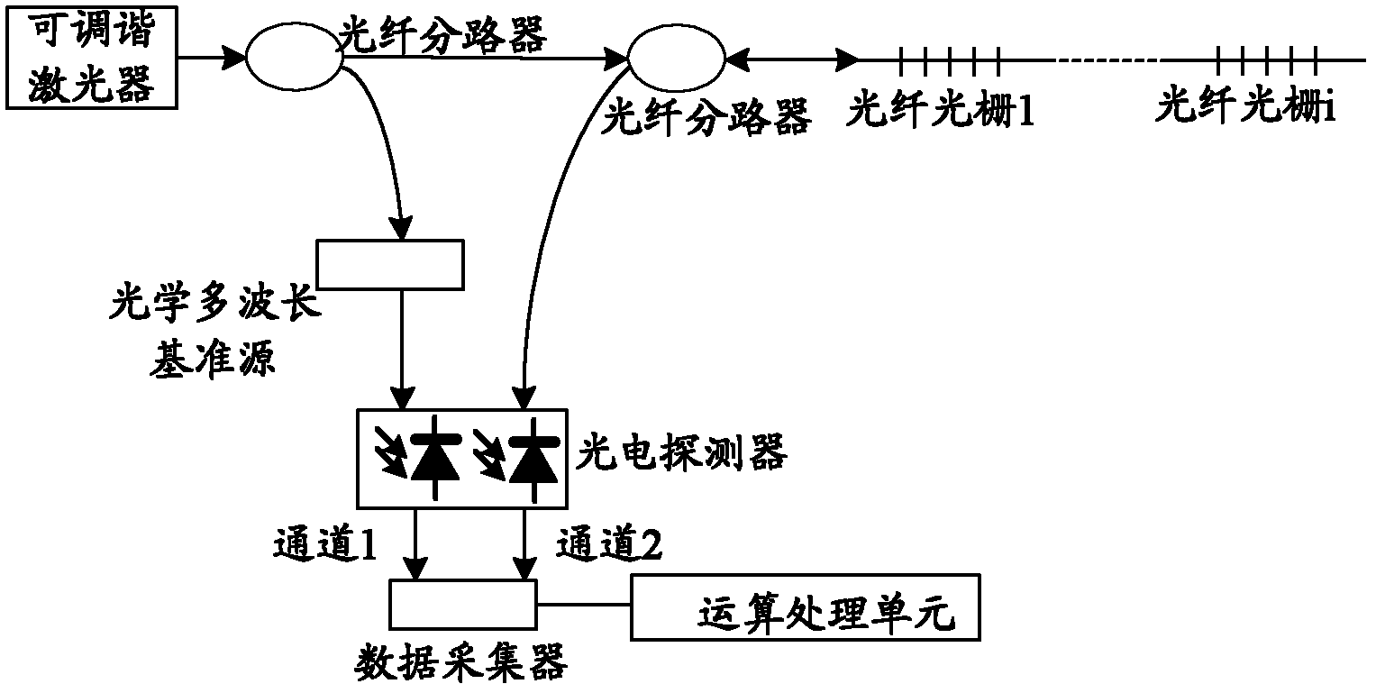
[0040] see Figure 5 As shown, it is a schematic structural diagram of the fiber grating wavelength synchronous demodulation system with ranging function of the present invention.

[0041] In one embodiment, the fiber grating wavelength synchronous demodulation system with ranging function includes: variable frequency scanning laser, optical multi-wavelength reference source, scanning laser output splitter group, n+1 second photoelectric A detector, m synchronous collectors and an operation processing unit.

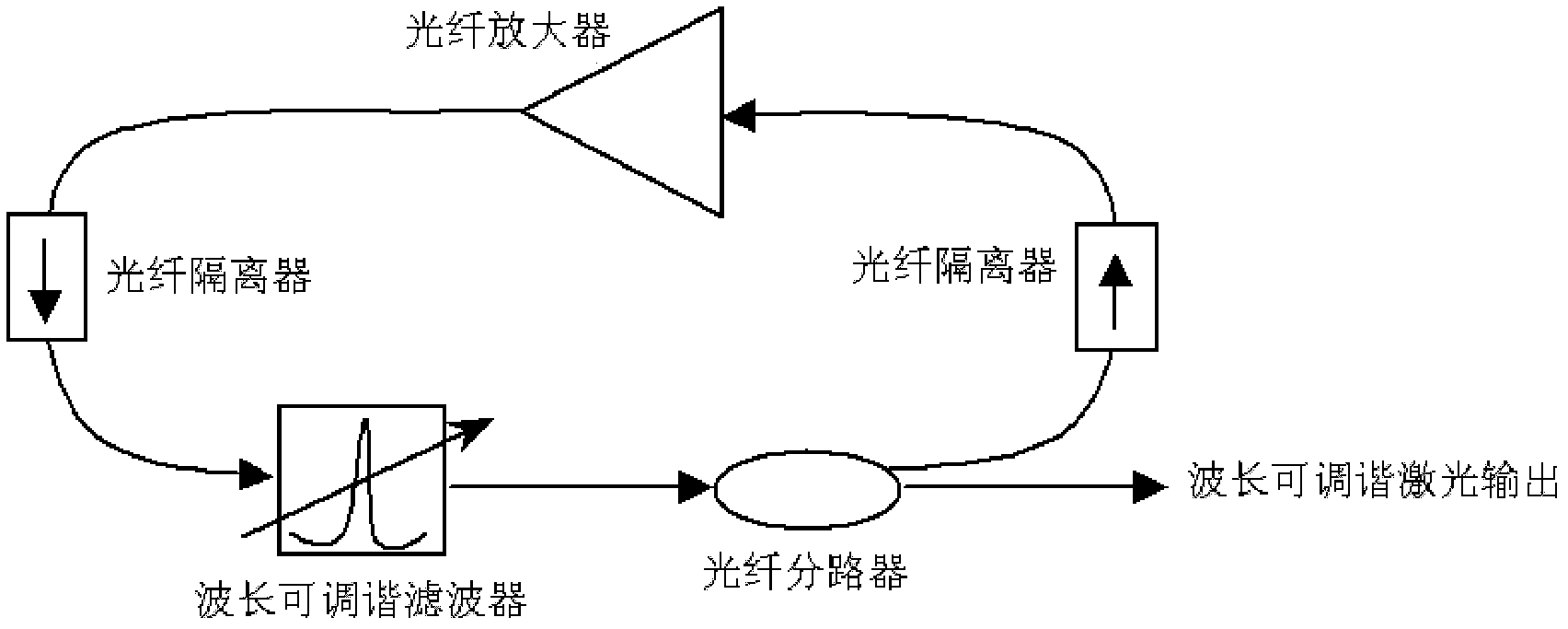
[0042] Wherein, the frequency-variable scanning laser instrument includes: a program-controlled signal source, a voltage amplifier and a ring fiber resonator, and the output end of the scanning triangle wave of the program-control signal source is connected to the input end of the ring fiber resonator through the voltage amplifier, The...


PUM


Abstract

The invention relates to a fiber grating wavelength synchronous demodulation system with a distance measurement function. The fiber grating wavelength synchronous demodulation system with the distance measurement function comprises a frequency conversion scanning laser instrument which can scan periodically in the range of a set wavelength, an optical multi-wavelength reference source, a scanning laser instrument output branching unit set, a multipath second photoelectric detector, a plurality of synchronous collectors, and an operation processing unit. The operation processing unit controls a scanning filter of the frequency conversion scanning laser instrument to successively work in two different scanning cycles, wavelength values of fiber gratings in the two different scanning cycles are demodulated, an accurate distance of optical fiber transmission is calculated according to the difference between two scanning triangular wave cycles sent by a stored program control signal source preset by the operation processing unit and the demodulated wavelength values of the fiber gratings, and then fiber grating wavelength demodulation error introduced by the optical fiber transmission distance is corrected, and therefore accurate spatial orientation and accurate wavelength demodulation of a fiber grating sensor are achieved. The fiber grating wavelength synchronous demodulation system with the distance measurement function has the advantages of being simple in structure, low in cost, and wide in application range.

Description

technical field [0001] The invention relates to the technical field of optical fiber sensing, in particular to the technical field of optical fiber sensing signal demodulation devices, and specifically refers to a fiber grating wavelength synchronous demodulation system with a ranging function. Background technique [0002] Fiber Bragg Grating (Fiber Bragg Grating) sensing technology is a sensing technology with high reliability, strong practicability and wavelength division multiplexing in optical fiber sensing. It adopts the laser irradiation method, and the laser spot with the center wavelength of 235nm to 248nm is adjusted by the lens and mirror for multiple times to form a rectangular laser spot with uniform distribution of light intensity, and then the laser spot is patterned with the help of a phase mask. Light and dark equiperiod diffraction fringes are formed along the axial direction of the quartz single-mode fiber, which eventually leads to periodic changes in the...

Claims


Application Information

Patent Timeline
Patent Type & Authority Applications(China)
IPC IPC(8): G01D5/26G02F2/00
Inventor 刘玉珏
Owner SHANGHAI BAIANTEK SENSING TECH CO LTD
Why Eureka
Try Eureka