
Eureka
For R&D, Eureka makes reading and utilizing patents & technical documents easy.
Eureka AIR
Designed for self-driven R&D workflows. Generate viable solutions, solve complex R&D challenges, empower your innovation with AI.

Eureka Materials
Designed for material experts only. Revolutionize your material R&D, from search, analyze, to developing new materials.

TechResearch
Generate reliable direction feasibility study reports for your R&D in just a few steps.

TechSeek
Discover and master advanced knowledge NOW. Basics, ideas, possibilities, all at once.

TechMind
As an expert in R&D Theories, TechMind can generates customized viable solutions instantly.

TechRisk
Analyze your overall solution with one click, know your potential R&D risks in advance.

TechMonitor
Get weekly tech updates, stay abreast of the latest tech innovations and key insights.
Micro-fluidic chip for droplet extraction
A microfluidic chip and droplet technology, which is applied in liquid solution solvent extraction, solvent extraction, laboratory containers, etc., can solve the problems of unfavorable liquid-liquid extraction and small specific surface area of droplets, and achieve good extraction effect, Good light transmittance and improved compatibility
- Summary
- Abstract
- Description
- Claims
- Application Information
AI Technical Summary
Problems solved by technology
Method used
Image

Examples
Embodiment 1
[0033] Embodiment 1, microfluidic chip
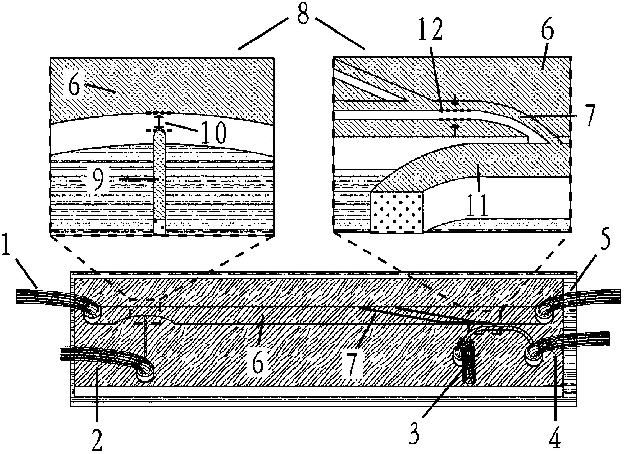
[0034] The structure of the present invention is illustrated by taking the direct droplet generation method and the diversion droplet recovery method as examples.
[0035] Such as figure 1 As shown, the microfluidic chip provided by the present invention includes a main channel 6, which is a linear channel, and one end of the main channel 6 is provided with a sample inlet (not marked in the figure), and the sample inlet communicates with the sample introduction tube 1, It is used to inject the sample solution; the other end of the main channel 6 is provided with a waste liquid outlet (not marked in the figure), and the waste liquid outlet is connected with the waste liquid outlet pipe 5 for exporting the waste liquid after extraction; At one end, the main channel 6 communicates with a side channel 9, and the free end of the side channel 9 is an extraction agent inlet (not marked in the figure), and the extraction agent inlet communicat...
Embodiment 2
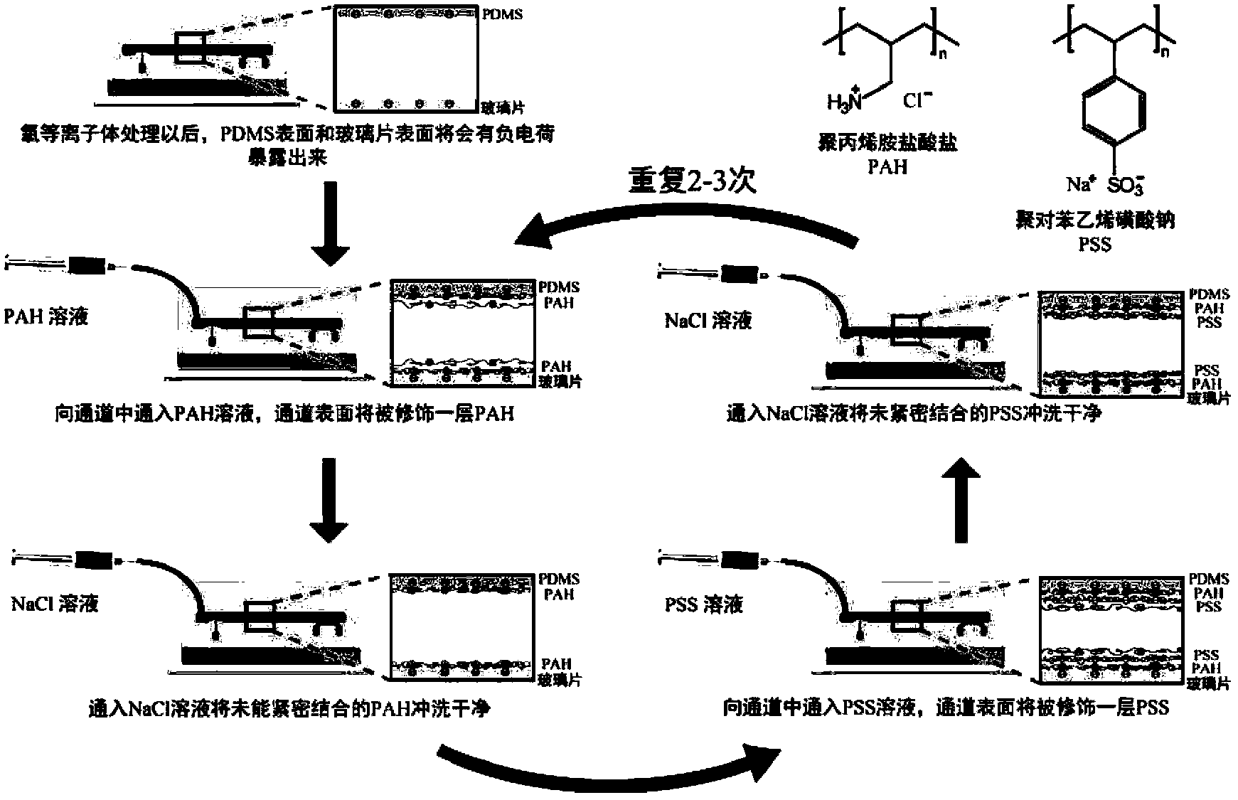
[0039] Embodiment 2, the hydrophilic modification of microfluidic chip
[0040] Such as image 3 As shown, after the microfluidic chip of the present invention is made, it can be modified by layer-by-layer self-assembly. After water-based, first pass through sodium chloride solution (containing 0.5M sodium chloride) containing 0.1% polyallylamine hydrochloride (PAH) for modification for 10 minutes, rinse with 0.1M sodium chloride solution, pass through containing 0.1 % polystyrene sulfonate (PSS) sodium chloride solution (containing 0.5M sodium chloride) modified for 10min, then washed again with 0.1M sodium chloride solution, and then passed through PAH and The sodium chloride solution of PSS is modified and repeated twice to modify the channel surface of the microfluidic chip to be hydrophilic and maintain it for a long time.
Embodiment 3
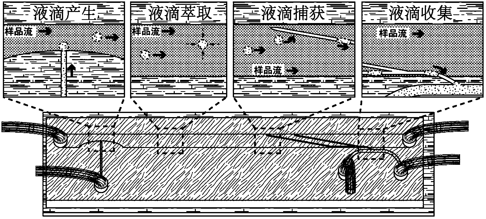
[0041] Example 3, the generation of droplets in the microfluidic chip of the present invention-direct droplet generation method
[0042] Such as Figure 4 As shown, the aqueous phase sample solution (simulated by the aqueous solution containing red dye) was passed into the main channel of the microfluidic chip at a flow rate of 5 μL / min, and at the same time, the flow rate of 1 μL / min was used to generate part of the microfluidic chip droplet The extractant solution (simulated by butanol) is passed into the side channel. When the extractant solution enters the main channel, it will be cut by the sample solution flowing in the main channel to form monodisperse droplets, which will flow forward with the sample solution. By adjusting the flow rate of the sample solution and the velocity of the extractant solution, the number and size of the droplets can be adjusted.
PUM
 Abstract
Description
Claims
Application Information
 - R&D Engineer
- R&D Manager
- IP Professional
- Industry Leading Data Capabilities
- Powerful AI technology
- Patent DNA Extraction
Browse by: Latest US Patents, China's latest patents, Technical Efficacy Thesaurus, Application Domain, Technology Topic, Popular Technical Reports.
© 2024 PatSnap. All rights reserved.Legal|Privacy policy|Modern Slavery Act Transparency Statement|Sitemap|About US| Contact US: help@patsnap.com