Surface-modified coated cutting tool and preparation method thereof

A cutting tool and surface modification technology, applied in the direction of tools, coatings, turning equipment for lathes, etc., can solve the problems of increasing the preparation process of coating cutting tools, increasing the production cost of tools, etc., to achieve processing performance and processing stability. Good performance, reduce processing cost, reduce the effect of friction and cutting force

Active Publication Date: 2013-07-17
ZHUZHOU CEMENTED CARBIDE CUTTING TOOLS CO LTD
View PDF10 Cites 20 Cited by
  • Summary
  • Abstract
  • Description
  • Claims
  • Application Information

AI Technical Summary

Problems solved by technology

The currently applied surface coating post-treatment process of cutting tools requires the coated blades to be connected in a series with different sizes of metal rods and isolation springs according to the specifications and models, and the distance between the two strings of coated blades is fixed. The distance is fixed on the tray bracket, and then the rotary table wet sandblasting machine is used to fully mix the aluminum oxide powder abrasive of a certain specification with water, set a certain air output

Method used


Image

  • Surface-modified coated cutting tool and preparation method thereof
  • Surface-modified coated cutting tool and preparation method thereof
  • Surface-modified coated cutting tool and preparation method thereof

Examples


Embodiment 1

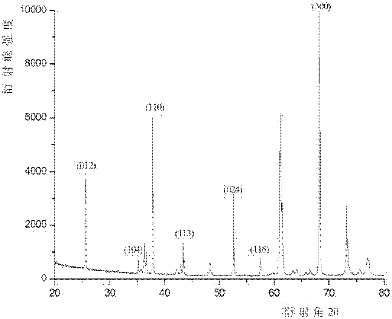
[0038] A cutting tool with a surface-modified coating of the present invention comprises a cemented carbide tool substrate and a coating, the tool substrate is coated with a coating, and the coating sequentially includes a TiN layer, a TiCN layer, a TiCO layer, α-Al 2 o 3 layer and Al(Zr) 2 o 3 Modified coating, Al(Zr) in coating 2 o 3 The modified coating has a corundum structure, Al(Zr) 2 o 3 The modified coating has obvious orientations in (110) and (300) crystal planes, and has a columnar structure with extremely smooth surface; Al(Zr) 2 o 3 The texture coefficients of the modified coatings in different orientations are shown in Table 1 below, where TC(110) is 1.92, TC(300) is 3.13, and (012), (104), (113), (024) , (116) crystal plane texture coefficients are ≤1. Al(Zr) 2 o 3 The surface roughness Ra of the modified coating was 0.21 μm. Al(Zr) on the upper and lower surfaces of the cutting tool in this embodiment 2 o 3 The thickness difference of the modified...

Embodiment 2

[0060] A cutting tool with a surface-modified coating of the present invention comprises a cemented carbide tool substrate and a coating, the tool substrate is coated with a coating, and the coating sequentially includes a TiN layer, a TiCN layer, a TiCO layer, α-Al 2 o 3 layer and Al(Zr) 2 o 3 Modified coating, Al(Zr) in coating 2 o 3 The modified coating has a corundum structure, Al(Zr) 2 o 3 The modified coating has obvious orientations in (110) and (300) crystal planes, and has a columnar structure with extremely smooth surface; Al(Zr) 2 o 3 The texture coefficients of the modified coatings in different orientations are shown in Table 4 below, where TC(110) is 3.04, TC(300) is 1.81, and in (012), (104), (113), (024) , (116) crystal plane texture coefficients are ≤1. Al(Zr) 2 o 3 The surface roughness Ra of the modified coating is 0.20 μm. Al(Zr) on the upper and lower surfaces of the cutting tool in this embodiment 2 o 3 The thickness difference of the modifi...


PUM

PropertyMeasurementUnit
Surface roughnessaaaaaaaaaa

Abstract

The invention discloses a surface-modified coated cutting tool and a preparation method thereof. The cutting tool comprises a tool substrate and a coating which is coated on the substrate. The coating comprises an Al(Zr)2O3 modification coating. The modification coating has obvious texture orientations on both (110) and (300) crystal planes, and has columnar structures with smooth surfaces. The preparation method provided by the invention comprises the steps that: a TiN layer, a TiCN layer, a TiCO layer, and an alpha-Al2O3 layer are sequentially deposited on the tool substrate by using an existing CVD process; and the following process conditions are used for depositing the modification coating: multiple gases are adopted as a deposition atmosphere system; deposition temperature and pressure are controlled, and atmosphere concentrations of specific gases are adjusted; deposition thickness is controlled; and coating surface post-treatment is not carried out after deposition is finished, and the coated cutting tool is directly obtained. The cutting tool provided by the invention has uniform surface thickness, extremely smooth coating surface, and improved microstructure and coating crystal plane orientation.

Description

technical field [0001] The invention belongs to the field of metal cutting, in particular to a coating cutting tool and a preparation method thereof. Background technique [0002] During the use of cutting tools, the failure phenomena of cutting tools include brittle chipping caused by mechanical shock and the wear, oxidation, adhesion and peeling of the tool under the combined action of mechanical and thermal cycle shocks. The emergence of coating technology provides an extremely effective way to solve problems such as tool toughness and wear resistance. [0003] Deposit one or more layers such as TiC, TiN, TiCN, Al on the surface of the tool substrate 2 o 3 Such as hard compound coating, which greatly improves the performance and service life of the cutting tool, making the cutting tool have higher wear resistance and heat resistance; the smooth surface of the tool also reduces the friction with the workpiece, reducing the Cutting force, reduced power consumption, energ...

Claims


Application Information

Patent Timeline
IPC IPC(8): C23C16/30B23B27/14
CPCC23C16/0272C23C16/40B23B27/14C23C16/30
Inventor 李秀萍陈响明王社权刘王平
Owner ZHUZHOU CEMENTED CARBIDE CUTTING TOOLS CO LTD
Why Eureka
Try Eureka