Efficient reburning denitrification device and technical method

A denitrification and high-efficiency technology, applied in the direction of improving energy efficiency, process efficiency, furnace, etc., can solve the problems of failing to meet nitrogen oxide emission standards, affecting the decomposition efficiency of raw materials, and high operating costs, so as to reduce denitrification Effects of operating costs, enhancing market competitiveness, and reducing denitrification costs

Active Publication Date: 2013-07-17
上海三融环保工程有限公司
View PDF9 Cites 15 Cited by
  • Summary
  • Abstract
  • Description
  • Claims
  • Application Information

AI Technical Summary

Problems solved by technology

[0002] At present, there are many flue gas denitrification processes in cement production lines, most of which have low denitrification efficiency and cannot meet the national nitrogen oxide emission standards; although the traditional selective non-catalytic reduction denitrification technology (SNCR) has been able to achieve relatively high denitrification abroad efficiency, but due to the use of ammonia water spraying, the operating cost remains high. At the same time, a large amount of ammonia water spraying will easily cause the temperature in the decomposition furnace to drop, which will affect the decomposition efficiency of raw materials. At the same time, unreacted ammonia will escape into the atmosphere and cause secondary pollution.

Method used


Image

  • Efficient reburning denitrification device and technical method
  • Efficient reburning denitrification device and technical method

Examples


Embodiment Construction

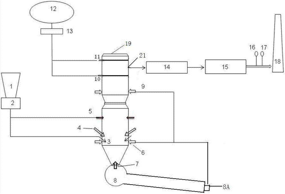
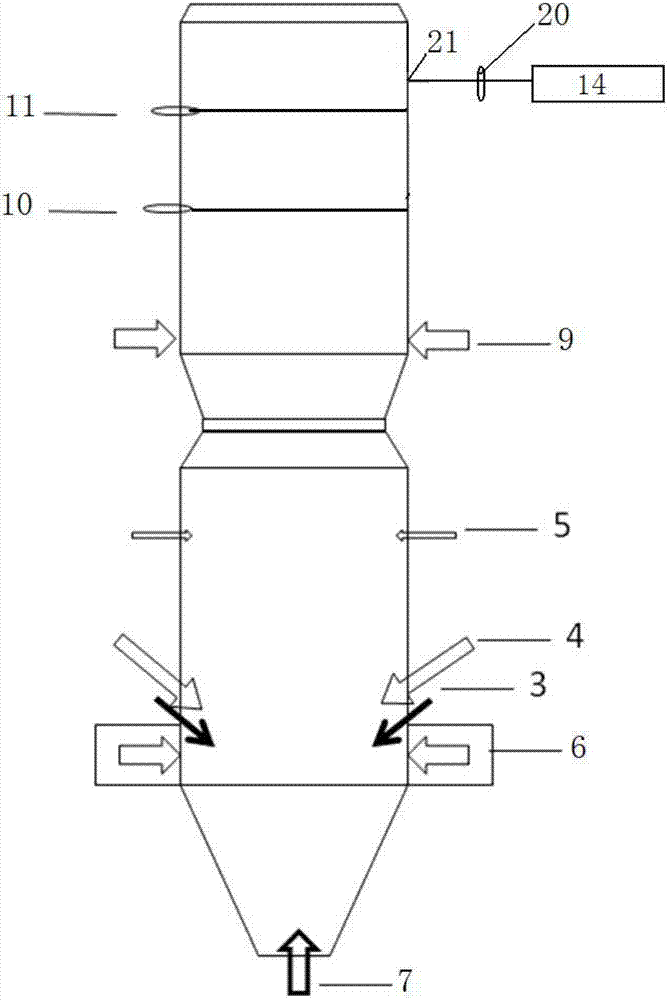
[0020] Such as figure 1 As shown, the raw meal enters the multi-stage cyclone preheater (not shown in the figure) after preparation and grinding, and enters the calciner 19 from the raw meal inlet 4 for decomposition, and the coal powder in the coal powder bin 1 is measured by the rotor scale 2 Then enter the main combustion zone from the low-nitrogen main burner 3 of the calciner 19, and contact with the high-temperature secondary air from the cement rotary kiln 8 (the high-temperature secondary air enters the main combustion zone from the secondary air inlet 7 at the bottom of the calciner 19) Afterwards, it begins to burn to release heat, and the main combustion zone needs a large amount of oxygen. Therefore, the tertiary air is taken from the cooler 8A position of the cement rotary kiln 8 and enters the main combustion zone from the tertiary air inlet 6 to ensure sufficient combustion (the tertiary air drawn from the cement rotary kiln 8 The wind provides oxygen for the co...


PUM


Abstract

The invention discloses an efficient reburning denitrification device which comprises a decomposing furnace. The bottom of the decomposing furnace is provided with a secondary air inlet and is connected with a rotary cement kiln. The decomposing furnace comprises a main low-nitrogen burner and a reburning burner on the lower portion from bottom to top, and a raw material inlet is arranged at the position of the main low-nitrogen burner. Coal powder in a coal powder bunker enters the decomposing furnace from the main low-nitrogen burner and the reburning burner. A tertiary air inlet is arranged below the raw material inlet and connected with a cooler of the rotary cement kiln. The decomposing furnace comprises an overfire air inlet and an SNCR (selective non-catalytic reduction) spray gun on the upper portion from bottom to top. The overfire air inlet is connected with the tertiary air inlet and the cooler of the rotary cement kiln. The SNCR spray gun is connected with a centrifugal pump and an ammonia water storage tank device. A smoke outlet is arranged at the upper section of the decomposing furnace and connected with a cyclone preheater, an electric dust collector and a chimney. The invention further provides a technical reburning denitrification method by the efficient reburning denitrification device. By the efficient reburning denitrification device and the technical reburning denitrification method, NOx removal efficiency can be improved, sprayed ammonia water is reduced, and denitrification cost of cement enterprises is lowered.

Description

technical field [0001] The invention relates to the field of environmental protection, in particular to flue gas denitrification of cement production lines, and in particular to a high-efficiency reburning denitrification (ERD) device and process. . Background technique [0002] At present, there are many flue gas denitrification processes in cement production lines, most of which have low denitrification efficiency and cannot meet the national nitrogen oxide emission standards; although the traditional selective non-catalytic reduction denitrification technology (SNCR) has been able to achieve relatively high denitrification abroad However, due to the use of ammonia water spraying, the operating cost remains high. At the same time, a large amount of ammonia water spraying will easily cause the temperature in the decomposition furnace to drop, which will affect the decomposition efficiency of raw materials. At the same time, unreacted ammonia will escape into the atmosphere ...

Claims


Application Information

Patent Timeline
Patent Type & Authority Applications(China)
IPC IPC(8): F27D17/00
CPCY02P10/25
Inventor 陈德志曾赐福
Owner 上海三融环保工程有限公司
Why Eureka
Try Eureka