Multi-vibroflot resonance ground treatment equipment and method

A technology of foundation treatment and vibrator, which is applied in the direction of infrastructure engineering, soil protection, construction, etc., can solve the problems of unsuitable deep foundation reinforcement, low bearing capacity, loose wind-blown sand on the upper part, etc., and achieve the elimination of uneven foundation performance, improve the bearing capacity of the foundation, and reduce the vibration amplitude

Active Publication Date: 2014-06-18
SHANGHAI HARBOUR SOFT SOIL TREATMENT ENG CO LTD +1
View PDF5 Cites 3 Cited by
  • Summary
  • Abstract
  • Description
  • Claims
  • Application Information

AI Technical Summary

Problems solved by technology

However, the geology of the sandy soil foundation has the following characteristics: first, the upper part of the eolian sand is very loose, with low and uneven bearing capacity, and poor engineering performance; second, the sand clay content is small and the cohesion between sand particles is poor. The void ratio is large and the water permeability is strong; the third is that the internal friction between the unsaturated sand particles is relatively large; the fourth is that the shallow groundwater is rich in reserves, etc.
Therefore, when the above-mentioned common foundation treatment methods are used to treat the sandy soil foundation, there are many problems such as high input cost, complicated construction technology, low construction efficiency, poor foundation reinforcement treatment effect, and unsuitability for deep foundation reinforcement. deficiencies and deficiencies
Therefore, the above-mentioned geological characteristics of the sandy soil foundation make all kinds of foundation treatment methods commonly used at present not fully applicable.

Method used


Image

  • Multi-vibroflot resonance ground treatment equipment and method

Examples


Embodiment 1

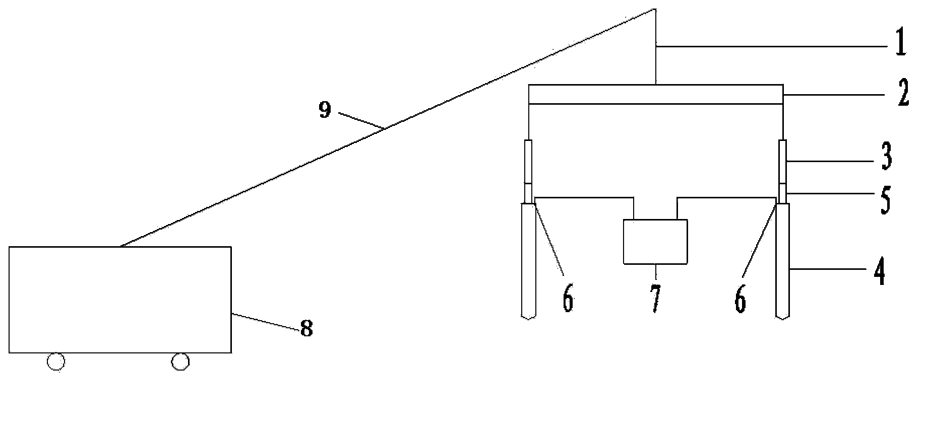
[0032] Such as figure 1 As shown, the vibration impactor resonance foundation treatment equipment with several heads in this embodiment includes a main body 8, a cantilever 9, a sling assembly 1, a channel steel 2, at least two steel cables 3 and a number of vibrating devices 4 corresponding to the steel cables 3 , the equipment main body 8 is connected to the sling assembly 1 through the cantilever 9, the sling assembly 1 is fixedly connected to the middle position of the channel steel 2, the two sides of the channel steel 2 are connected to at least two evenly arranged steel cables 3, and the steel cables 3 The bottom is fixedly connected with the corresponding vibrating device 4. The vibrating device 4 is a vibrator with a deflection rotor driven by a motor inside. The vibrating device 4 is provided with a water inlet 6, and the water inlet 6 is connected to the high-pressure water pump. 7 connection, each vibration device 4 and the steel cable 3 are provided with buffer an...

Embodiment 2

[0037] A sandy soil foundation with a thickness of 10-12 meters, a clay content of 7.5%, and a permeability coefficient of 10 -3 cm / s.

[0038] Design requirements: The bearing capacity of the 12-meter sandy soil foundation reaches 100KPa.

[0039] Step 1: measure the compacted depth of the sand layer: according to the conventional method, measure the compacted depth of the sand layer on the constructed sandy soil foundation, and the compacted depth of the sand layer is 3 meters;

[0040] Step 2: Vibration construction: use the vibro impactor resonance foundation treatment equipment described in Example 1, the bottom of the channel steel is connected to the corresponding vibrating device through two steel cables, and the distance between two adjacent vibrating devices is 2 meters , each vibrating device is connected with a high-pressure water pump, and several locations to be constructed are selected on the sandy soil foundation to be constructed. are the same, and for any l...

Embodiment 3

[0050] A sandy soil foundation with a thickness of 18-25 meters, a clay content of 8.5%, and a permeability coefficient of 2×10 -3 cm / s.

[0051] Design requirements: The bearing capacity of the 18-meter sandy soil foundation reaches 120KPa.

[0052] Step 1: measure the compacted depth of the sand layer: according to the conventional method, measure the compacted depth of the sand layer on the constructed sandy soil foundation, and the compacted depth of the sand layer is 15 meters;

[0053] Step 2: Vibration construction: use the vibro impactor resonance foundation treatment equipment described in Example 1, the bottom of the channel steel is connected to the corresponding vibrating device through three steel cables, the three vibrating devices are distributed in a triangle, and the three vibrating devices The distance between the devices is 5 meters, and each vibrating device is connected with a high-pressure water pump. On the sandy soil foundation to be constructed, sever...


PUM


Abstract

The invention discloses multi-vibroflot resonance ground treatment equipment and a multi-vibroflot resonance ground treatment method, and relates to the technical field of sandy soil ground treatment. The equipment comprises an equipment main body, a cantilever, a suspension cable component, channel steel, at least two steel ropes and vibration devices in a number which corresponds to that of the steel ropes, wherein the equipment main body is connected with the suspension cable component through the cantilever; the suspension cable component is fixedly connected with the middle position of the channel steel; the two sides of the channel steel are connected with the at least two uniformly distributed steel ropes; the lower parts of the steel ropes are fixedly connected with the corresponding vibration devices; the vibration devices are vibroflots in which skewed rotors driven by motors are arranged, and are provided with water inlets which are connected with a high-pressure water pump; and a buffering vibration-proof gasket is arranged between each vibration device and the corresponding steel rope. The construction method is simple, the equipment and the method are rational in design, convenient to implement, low in construction cost and high in working efficiency, can be effectively applied to a sandy soil ground treatment process, and have good treatment effects, and the construction quality is easily ensured.

Description

technical field [0001] The invention relates to the technical field of sandy soil foundation treatment, in particular to a multi-head vibrator resonance foundation treatment equipment and a method thereof. Background technique [0002] At present, the commonly used foundation treatment methods mainly include water fall sand replacement, dynamic compaction, cement mixing pile, lime-soil compaction pile, vibratory impact compaction method suitable for treating medium sand and coarse sand foundations with clay content not greater than 10%. Wait. However, the geology of the sandy soil foundation has the following characteristics: first, the upper part of the eolian sand is very loose, with low and uneven bearing capacity, and poor engineering performance; second, the sand clay content is small, and the cohesion between sand particles is poor. The void ratio is large and the water permeability is strong; the third is that the internal friction between the unsaturated sand partic...

Claims


Application Information

Patent Timeline
Patent Type & Authority Patents(China)
IPC IPC(8): E02D3/054
Inventor 徐士龙徐望
Owner SHANGHAI HARBOUR SOFT SOIL TREATMENT ENG CO LTD
Why Eureka
Try Eureka