Supercharge Your Innovation With Domain-Expert AI Agents!

Waste heat recycling system for ceramic kilns

A ceramic kiln and waste heat recovery technology, applied in furnaces, waste heat treatment, furnace components, etc., can solve the problems of insufficient utilization and insufficient utilization of hot water

Active Publication Date: 2013-08-14
FOSHAN DONGPENG CERAMIC +3
View PDF6 Cites 0 Cited by
  • Summary
  • Abstract
  • Description
  • Claims
  • Application Information

AI Technical Summary

Problems solved by technology

There are not many places where heat is used in the entire process of ceramic manufacturing. The reason why the waste heat of the kiln that is easily recovered cannot be fully utilized is because the inertial thinking of people in the field believes that hot water cannot be fully utilized in other process steps.

Method used


Image

  • Waste heat recycling system for ceramic kilns
  • Waste heat recycling system for ceramic kilns
  • Waste heat recycling system for ceramic kilns

Examples


Embodiment Construction

[0023] The technical solutions of the present invention will be further described below in conjunction with the accompanying drawings and through specific implementation methods.

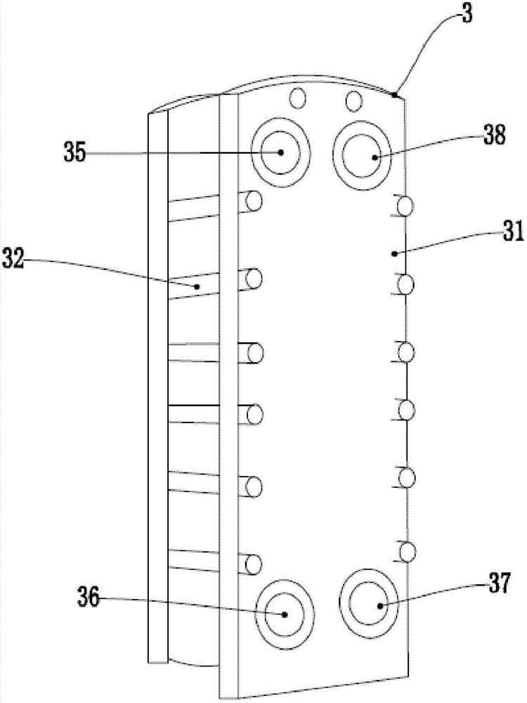
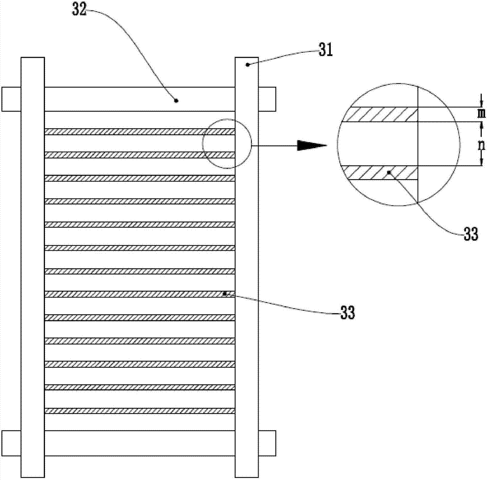
[0024] The plate heat exchanger 3 is composed of concave and convex stainless steel heat exchange plates 33 formed by stamping. The hot water and slurry are respectively on both sides of the heat exchange plates 33, and the concave and convex lines between adjacent heat exchange plates 33 are combined at 180 degrees. Therefore, the concave and convex ridges between the heat exchange plates 33 form staggered contact points, and these staggered flow structures make the hot and cold fluids in the plate heat exchanger 3 generate strong turbulence to achieve high heat exchange effect. Plate heat exchanger 3 is a commonly used heat exchanger in industry, but no one has ever applied it to the heating process of ceramic slurry.

[0025] Ceramic powder is formed from raw materials through processes such as b...


PUM

PropertyMeasurementUnit
thicknessaaaaaaaaaa
thicknessaaaaaaaaaa
thicknessaaaaaaaaaa

Abstract

A waste heat recycling system for ceramic kilns comprises the ceramic kilns, water pipes, plate heat exchangers and slurry pipes. Heating sections of the water pipes are mounted below roll bars of slow cooling sections of the ceramic kilns, and penetrate through the ceramic kilns in a zigzag reciprocating manner, and pipelines exposed out of the ceramic kilns are wrapped by heat-insulation layers; heat exchange sections of the water pipes and the slurry pipes are subjected to heat exchange at the plate heat exchangers; the water pipes and the plate heat exchangers are subjected to countercurrent heat exchange; and distances among plates of the plate heat exchangers range from 1.5mm to 3.5mm, and the thickness of each stainless steel heat exchange plate of each plate heat exchanger ranges from 0.5mm to 1.5mm. The waste heat recycling system has the advantages that the technical difficult problem of utilizing waste heat of kilns to heat slurry is solved, and waste heat of the kilns can be sufficiently utilized in a ceramic manufacturing process owing to characteristics of the short distances among the plates, large heat exchange areas, sufficient disturbance in a water and slurry flowing procedure and extremely high heat exchange efficiency of the plate heat exchangers.

Description

technical field [0001] The invention relates to the technical field of energy saving and environmental protection in the ceramic industry, in particular to a waste heat recovery and utilization system of a ceramic kiln. Background technique [0002] Ceramics are fired at a temperature of 1200°C. The long ceramic kiln has many rollers from the entrance to the exit. The ceramic blank moves slowly on the rollers and is fired when it reaches the exit. The air heat energy in the kiln can be completely recycled, and there are currently two ways to recover the waste heat of the kiln. One is to recover hot air, such as the Chinese utility model patent whose authorized notification number is CN201152691Y, which adopts an induced draft fan to draw hot air from a kiln to dry the blank. The other is hot water recovery. For example, the invention patent application with the application publication number CN102313455A installs several water tanks on the top of the slow-cooling rear secti...

Claims


Application Information

Patent Timeline
Patent Type & Authority Applications(China)
IPC IPC(8): F27D17/00
CPCY02P10/25
Inventor 王业豪邝志均陈苏松周燕
Owner FOSHAN DONGPENG CERAMIC
Features
  • R&D
  • Intellectual Property
  • Life Sciences
  • Materials
  • Tech Scout
  • Unparalleled Data Quality
  • Higher Quality Content
  • 60% Fewer Hallucinations
Learn More