
Plasma fluid bed gasifying device

A technology of fluidized bed gasification and fluidized bed gasification furnace, applied in the direction of granular/powdered fuel gasification, etc., can solve the problems of large resource consumption, high waste gas, low gasification rate, etc., and achieve fast gasification speed , high gasification efficiency and low waste gas ratio

Inactive Publication Date: 2013-09-04
衢州市广源生活垃圾液化技术研究所
View PDF3 Cites 8 Cited by
  • Summary
  • Abstract
  • Description
  • Claims
  • Application Information

AI Technical Summary

Problems solved by technology

[0006] The purpose of the present invention is to overcome the shortcomings of conventional gasification furnaces, such as low gasification rate, high resource consumption, and large waste gas, and to design a plasma fluidized bed gasification device for coal gasification, domestic garbage gasification or Biomass gasification to produce high-quality hydrogen-rich synthesis gas, and realize the reduction of greenhouse gas emissions and the elimination of dioxin pollution. The hydrogen-rich synthesis gas produced is used as the raw material gas for the subsequent production of methanol or dimethyl ether

Method used


Image

  • Plasma fluid bed gasifying device
  • Plasma fluid bed gasifying device
  • Plasma fluid bed gasifying device

Examples


Embodiment 1

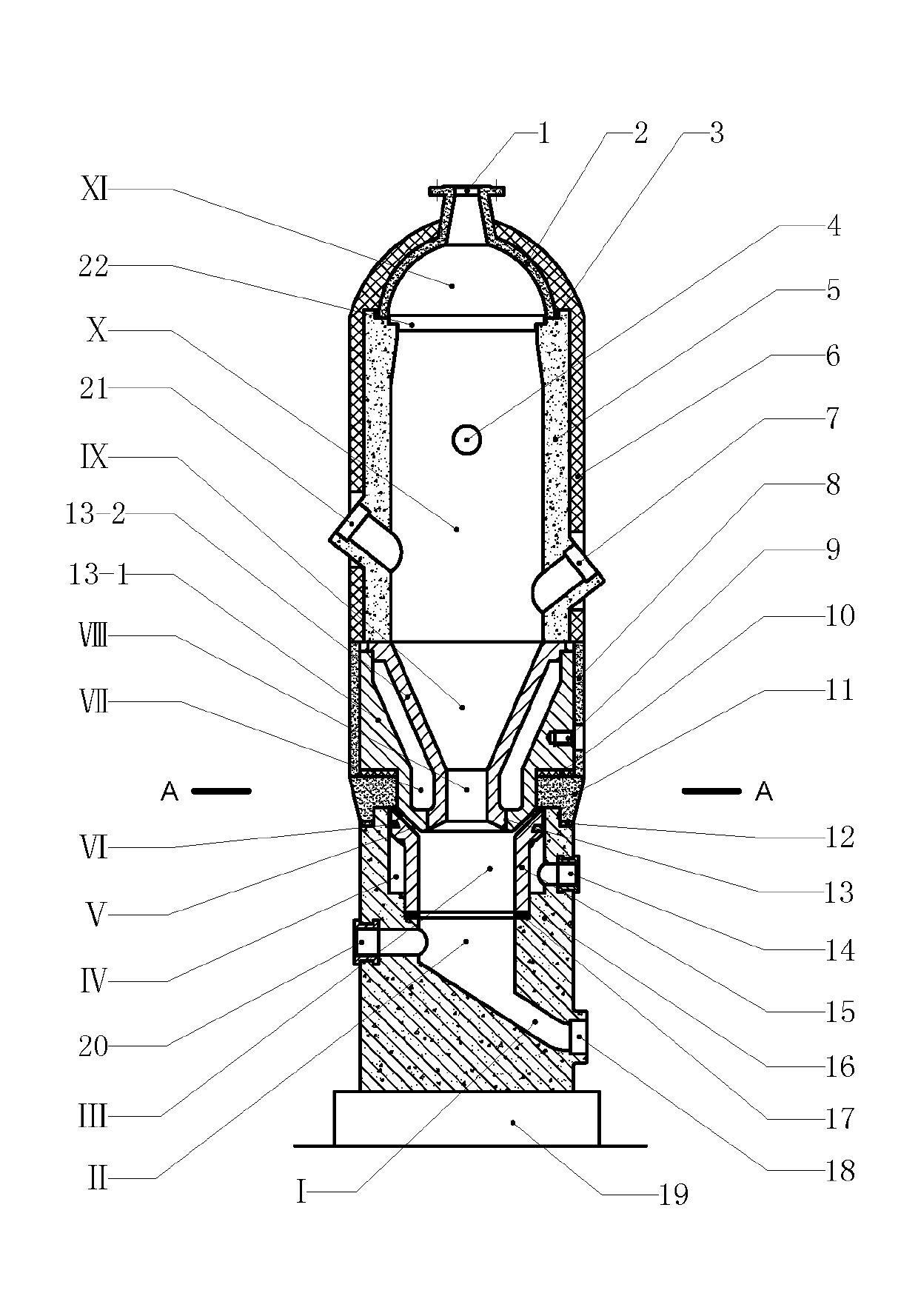
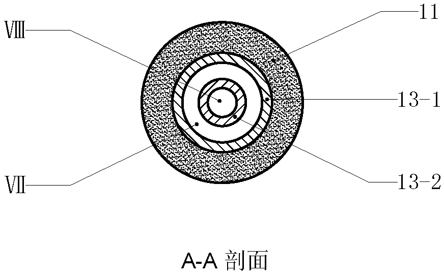
[0030] Example 1 figure 1 In the embodiment shown, the plasma fluidized bed gasifier mainly consists of a top cover (2), an upper furnace body, an insulating connector (11), a lower furnace body (16), an anode (13), and a cathode (15) and the base (19), wherein the top cover (2), the upper furnace body, the anode (13), the insulating connector (11), the lower furnace body (16) and the base (19) are arranged sequentially from top to bottom The cathode (15) is arranged in the upper inner space of the lower furnace body (16), and the inner space in the middle part of the lower furnace body (16) constitutes the gasification agent chamber (II), and the gasification agent chamber (II) has a gasification agent input interface ( 20) access, the lower part of the lower furnace body (16) has a slag discharge channel (I), the slag discharge channel (I) communicates with the gasification agent chamber (II), and the slag discharge channel (I) has a slag discharge port (18) The cathode (15...

Embodiment 2

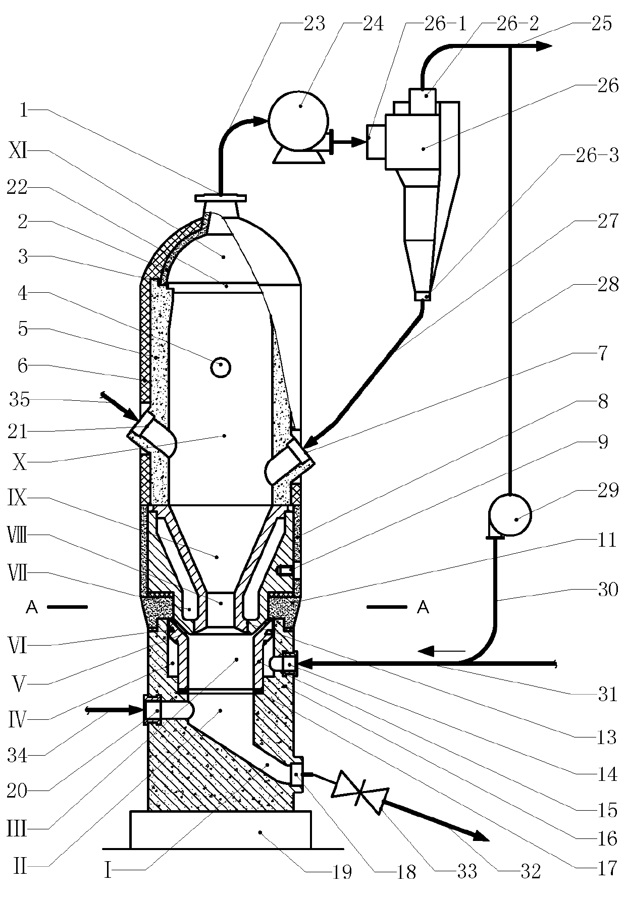
[0031] Example 2 figure 2 In the embodiment shown, the plasma fluidized bed gasification device is composed of a plasma fluidized bed gasifier and equipment outside the furnace, wherein the structure of the plasma fluidized bed gasifier is as described in Example 1, I won’t go into details here; the peripheral equipment mainly includes high-temperature gas blower (24), cyclone separator (26) and syngas delivery pipe (25), and the syngas output interface (1) of plasma fluidized bed gasifier is connected to the The air inlet of the gas fan (24), the air outlet of the high-temperature gas fan (24) are connected to the mixture inlet (26-1) of the cyclone separator (26), and the gaseous substance outlet (26-2) of the cyclone separator (26) Connected to the syngas delivery pipe (25), the solid matter outlet (26-3) of the cyclone separator (26) is connected to the charcoal ash return interface (7); the working gas input interface of the plasma fluidized bed gasifier ( 14) There is ...


PUM

PropertyMeasurementUnit
particle diameteraaaaaaaaaa

Abstract

The invention relates to a plasma fluid bed gasifying device, relating to plasma gasification furnace equipment. The plasma fluid bed gasifying device mainly comprises a top cover, an upper furnace body, an insulated connecting piece, a lower furnace body, an anode, a cathode and a base, wherein the cathode is arranged in an inner space at the upper part of the lower furnace body; the upper cylindrical end of the cathode is in a horn mouth shape; the outer edge of the horn mouth is provided with a spiral groove; the insulated connecting piece is arranged between the anode and the lower furnace body; through holes in the axle center of the anode form a compressed hole channel; a horn mouth at the outlet of the compressed hole channel forms an anode arc root zone; the anode is internally provided with a cooling water sleeve; the upper furnace body is arranged on the anode; the inner space of the upper furnace body forms a gasification zone; and the top cover is provided with a synthesis gas output port for outputting synthesis gas. The plasma fluid bed gasifying device utilizes the characteristics that gasification raw materials of a fluid bed are wide in adaptability and high-temperature particles move seriously inside the gasification zone so as to strengthen heat transfer, and meanwhile, high-temperature working air at more than 4000 DEG C is taken as fluidized wind, so that coal or garbage biomass is quicker in gasification, higher in gasification efficiency and lower in energy consumption, and hydrogen-enriched synthesis gas with higher quality can be obtained.

Description

technical field [0001] The invention relates to gasification equipment, in particular to a plasma gasification furnace equipment. Background technique [0002] At present, in conventional coal gasification devices, water vapor + air or water vapor + oxygen are sent into the gasification furnace as a gasification agent, so that water vapor and coal undergo a gas-forming reaction to generate synthesis gas. The reaction is an endothermic reaction, which requires air Or the oxidation reaction between oxygen and carbon will provide heat for it. This gasification method will increase the consumption of coal resources. At the same time, a large amount of carbon dioxide waste gas will be generated in the synthesis gas, which will not only affect the quality of the synthesis gas, but also cause a large amount of emissions in the subsequent production. of greenhouse gases. [0003] With the improvement of people's living standards and the development of cities, the amount of domestic...

Claims


Application Information

Patent Timeline
Patent Type & Authority Applications(China)
IPC IPC(8): C10J3/56
Inventor 周开根
Owner 衢州市广源生活垃圾液化技术研究所
Learn More