Intelligent power module for three-phase bridge type drive

A technology of intelligent power modules and drive modules, applied in the direction of output power conversion devices, electrical components, electric solid devices, etc., can solve the problems of high heat generation, complicated process, unfavorable production and reliability control of power devices

Active Publication Date: 2013-09-04
NINGBO SEMICON INT CORP
View PDF5 Cites 3 Cited by
  • Summary
  • Abstract
  • Description
  • Claims
  • Application Information

AI Technical Summary

Problems solved by technology

[0004] In existing applications, a three-phase bridge drive intelligent power module usually uses a power module integration method to integrate a single gate drive chip and six power devices (including six freewheeling diodes) into one module. , on the one hand, in the manufacture of intelligent power module devices, due to the large area of ​​the six power devices and the large heat generated by the power devices during operation, it is often required that the distance between each power device be large during assembly, and the grid Compared with the area of ​​the power device, the area of ​​the pole driver chip is often very small, so the metal connecting wires from the gate driver chip to each power device will be very long, and a PCB with high thermal conductivity needs to be added for packaging. At the same time, due to the long metal connecting wires connecting the output end of the gate drive chip to the power device, it is susceptible to signal interference, which greatly reduces the reliability of the intelligent power module, which is not conducive to production and reliability control; on the other hand, the gate The manufacturing cost of the electrode driver chip is affected by the process manufacturing technology. Since the gate driver chip needs t

Method used


Image

  • Intelligent power module for three-phase bridge type drive
  • Intelligent power module for three-phase bridge type drive
  • Intelligent power module for three-phase bridge type drive

Examples


Embodiment 1

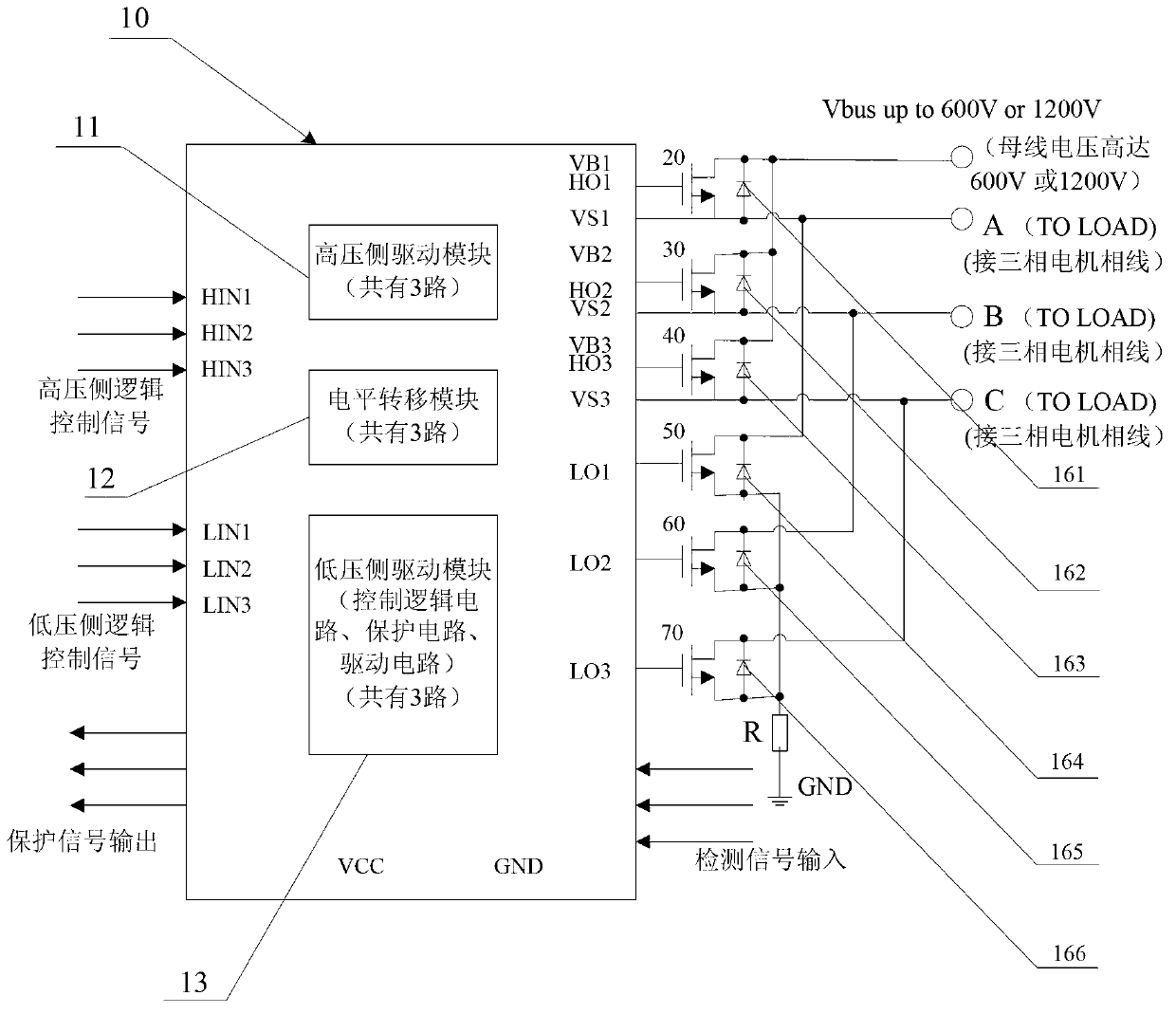
[0033] An intelligent power module for three-phase bridge drive proposed in this embodiment, its circuit schematic diagram is as follows figure 2 As shown, it mainly includes a gate drive chip, three high-voltage side power devices 20, 30, 40, three low-voltage side power devices 50, 60, 70 and six freewheeling diodes 161, 162, 163, 164, 165, 166. For some power devices, if the freewheeling diode is integrated inside the power device, the freewheeling diode in this scheme is no longer needed. The gate drive chip is mainly composed of a high-voltage side control drive chip 180 produced by a high-voltage isolation manufacturing process and a low-voltage side control drive chip 120 produced by a CMOS process. The high-voltage side control drive chip 180 is mainly composed of a high-voltage side drive module with three inputs and outputs. 181 is integrated with a three-way input-output level shift module 182. The low-voltage side control driver chip 120 is mainly integrated by a ...

Embodiment 2

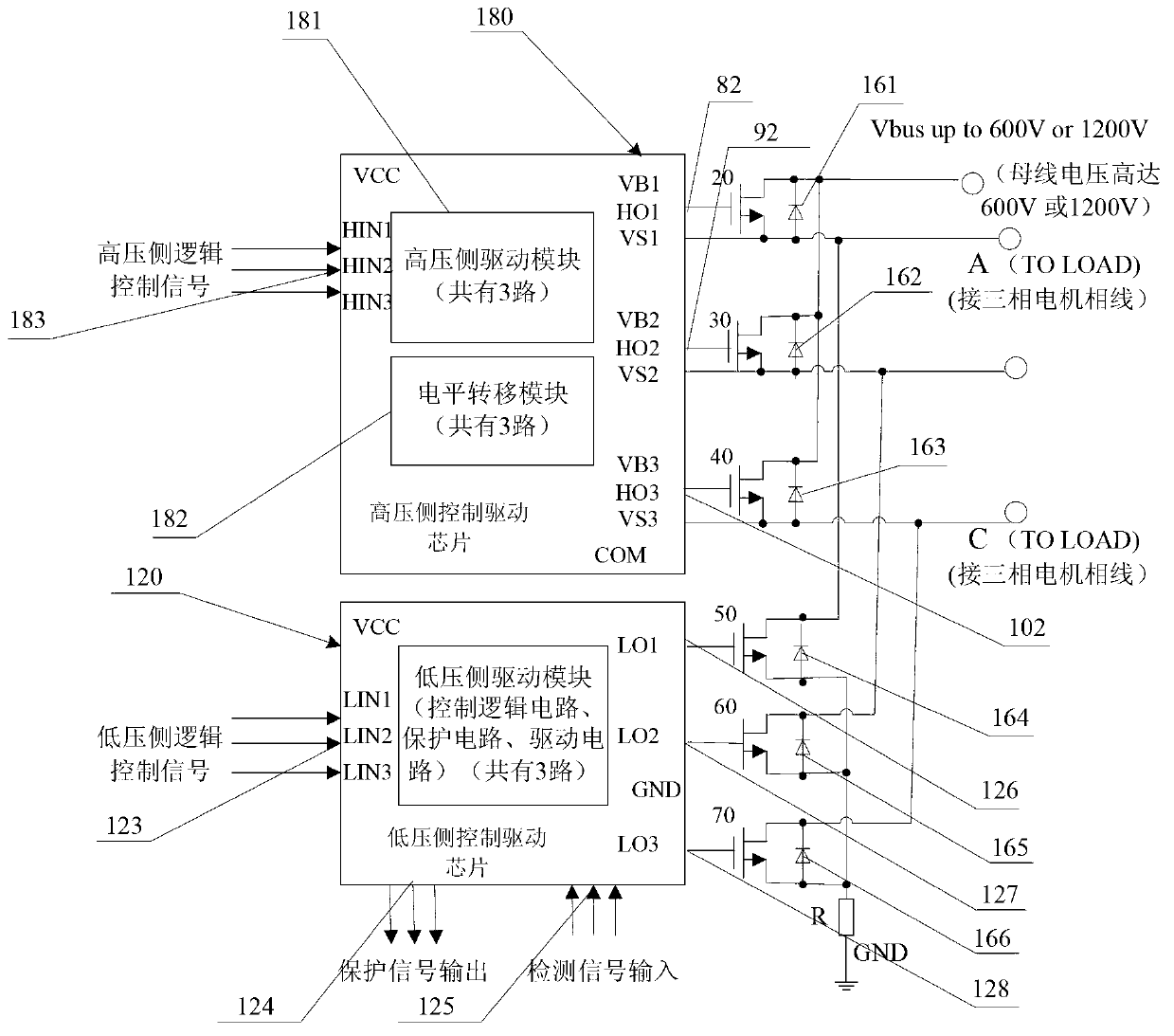
[0043] An intelligent power module for three-phase bridge drive proposed in this embodiment, its circuit schematic diagram is as follows image 3 As shown, the difference from Embodiment 1 is that the level shifting module is integrated separately, and the three circuits of the high-voltage side driving module are separately integrated.

[0044] The intelligent power module of this embodiment mainly includes a gate drive chip, three high-voltage side power devices 20, 30, 40, three low-voltage side power devices 50, 60, 70, and six freewheeling diodes 161, 162, 163, 164 , 165, 166, for some power devices, if the freewheeling diode is integrated inside, the freewheeling diode in this embodiment is no longer needed. The gate drive chip is mainly composed of a level shift chip 110 produced by a high-voltage isolation manufacturing process, three high-voltage side control drive chips 80, 90, and 100 produced by a CMOS process, and a low-voltage side control drive chip 120. The lev...

Embodiment 3

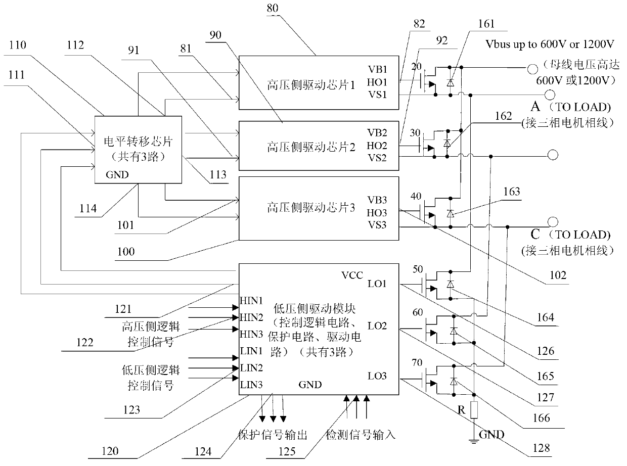
[0050] An intelligent power module for three-phase bridge drive proposed in this embodiment, its circuit schematic diagram is as follows Figure 4 As shown, the difference between it and the intelligent power module given in Embodiment 2 is that the three-way level shift chip is divided into three one-way level shift chips.

[0051] The intelligent power module of this embodiment mainly includes a gate drive chip, three high-voltage side power devices 20, 30, 40, three low-voltage side power devices 50, 60, 70, and six freewheeling diodes 161, 162, 163, 164 , 165, 166, for some power devices, if a freewheeling diode is integrated inside, the freewheeling diode in this embodiment is no longer needed. The gate drive chip is mainly composed of three level shift chips 130, 140, 150 produced by high-voltage isolation manufacturing process, three high-voltage side control drive chips 80, 90, 100 produced by CMOS process, and one low-voltage side control drive chip 120 Each level sh...


PUM


Abstract

The invention discloses an intelligent power module for three-phase bridge type drive. A conventional chip integrated with a high-voltage side driver module, a level shifter module and a low-voltage side driver module is redivided into a level shifter chip, a high-voltage side control driver chip and a low-voltage side control driver chip, the complex high-voltage isolation production technique is adopted to only produce the level shifter chip, the ordinary CMOS (complementary metal oxide semiconductor) technique is adopted to produce the high-voltage side control driver chip and the low-voltage side control driver chip, therefore the ordinary CMOS technique integrated with the high-voltage isolation production technique does not need to be adopted to product each chip, and each chip, power devices and fly-wheel diodes are then packaged together to form the intelligent power module for three-phase bridge type drive. The production process of the level sifter chip of the intelligent power module can be more easily controlled, which can help to increase the yield rate; moreover, the area of the high-voltage side control driver chip and the low-voltage side control driver chip can be small, and the yield rate of production can be guaranteed.

Description

[0001] This application is a divisional application of the original application number 201110203093.4 for a patent application for invention. Its application date is July 20, 2011. The title of the invention is "an intelligent power module for three-phase bridge drive". technical field [0002] The invention relates to an intelligent power module in motor drive, in particular to an intelligent power module for three-phase bridge drive. Background technique [0003] The intelligent power module is a commonly used module in the field of motor drive. The bridge driver chip in the intelligent power module is generally a half-bridge driver chip, a full-bridge driver chip or a three-phase bridge driver chip. Two half-bridge driver chips can be combined A full-bridge driver chip can be formed, and three half-bridge driver chips can be combined into a three-phase bridge driver chip. Among them, the three-phase bridge drive chip is often used in frequency conversion products of three...

Claims


Application Information

Patent Timeline
IPC IPC(8): H02M1/088H01L25/16
Inventor 胡同灿
Owner NINGBO SEMICON INT CORP
Why Eureka
Try Eureka