Methods of Applying Thermal Barrier Coatings

A technology of thermal barrier coatings and ceramic coatings, applied in coatings, separation methods, plating of superimposed layers, etc., can solve the problems of low tensile resistance, easy peeling, and expensive thermal barrier coatings applied by EB-PVD and other problems, to achieve the effect of improved tensile resistance and low-cost application

Active Publication Date: 2018-09-07
FORSCHUNGSZENTRUM JULICH GMBH +1
View PDF6 Cites 0 Cited by
  • Summary
  • Abstract
  • Description
  • Claims
  • Application Information

AI Technical Summary

Problems solved by technology

Thin thermal barrier coatings applied by APS have the disadvantage that they have relatively low stretch tolerance and tend to peel off under cyclic thermal strain
[0013] However, the preparation of the thermal barrier coating structure described in US 5,238,752 has the following disadvantages: the equipment cost for applying the thermal barrier coating by EB-PVD is relatively high, and the application speed is low, so that the application by EB-PVD Applying a thermal barrier coating is relatively expensive

Method used


Image

  • Methods of Applying Thermal Barrier Coatings
  • Methods of Applying Thermal Barrier Coatings
  • Methods of Applying Thermal Barrier Coatings

Examples


Embodiment Construction

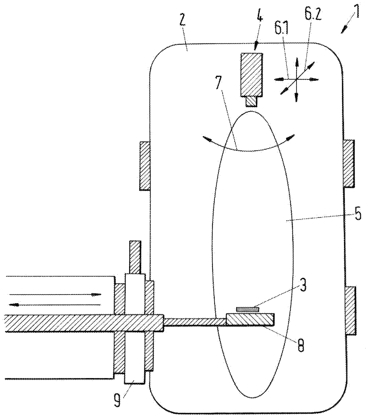
[0043] figure 1 An embodiment of a plasma coating apparatus for applying a thermal barrier coating of the present invention is shown. The plasma coating device 1 comprises a working chamber 2 with a plasma torch 4 for generating a plasma jet 5, figure 1 A control pump device, not shown, connected to the working chamber 2 to set the pressure in the working chamber, and a substrate holder 8 (holder) for supporting the substrate 3 . The plasma torch 4 can be designed, for example, as a DC plasma torch, which advantageously has a supply power of at least 60 kW or at least 80 kW or at least 100 kW to generate a plasma with a sufficiently high specific enthalpy to enable the production of thermal barrier coatings with columnar structures. The pressure in the working chamber 2 can be conveniently set between 2Pa to 100kPa or 5Pa to 20kPa. If desired, the plasma coating apparatus 1 may additionally comprise one or more injection devices for injecting one or more components in solid,...


PUM

PropertyMeasurementUnit
thicknessaaaaaaaaaa
thicknessaaaaaaaaaa
thicknessaaaaaaaaaa

Abstract

To apply the thermal barrier coating (10), a plasma jet (5) is generated in the working chamber (2) by a plasma torch and directed towards the surface of the substrate (3) introduced into the working chamber, where it is deposited on the substrate by PS‑PVD A ceramic coating is applied to the surface, wherein the coating is injected as a powder into the plasma jet and partially or completely vaporized therein. When applying a thermal barrier coating, in the first working step, the feed rate of the injected powder is set such that most of the injected powder is vaporized, wherein the coating condenses from the gas phase onto the surface of the substrate and is bonded to the surface of the substrate. The materials form a mixed phase. In a second working step, the feed rate of the infused powder is increased by at least 5 times, so that the relative proportion of vaporized infused powder is reduced and the coating is deposited in the form of elongated columns, which create an anisotropic microstructure and are oriented substantially perpendicular to the substrate surface.

Description

technical field [0001] The invention relates to a method for applying a thermal barrier coating on the surface of a substrate according to the preamble of claim 1 and to a substrate with such a thermal barrier coating. Background technique [0002] Thermal barrier coatings are used in machinery and processes to protect components subjected to high thermal strains from heat, hot gas corrosion and erosion. Increases in mechanical and process efficiency can often only be achieved by increasing process temperatures, so that exposed components must be protected accordingly. Thus, turbine blades, for example in aeroengines and stationary gas turbines, are often provided with thermal barrier coatings or multi-layer thermal barrier coating systems to protect the turbine blades from thermal process temperatures and to extend maintenance intervals and service life . [0003] Depending on the application, thermal barrier coating systems may comprise one or more layers such as barrier...

Claims


Application Information

Patent Timeline
Patent Type & Authority Patents(China)
IPC IPC(8): C23C14/22C23C14/08C23C14/16
CPCC23C14/027C23C14/083C23C14/228C23C28/30C23C4/134Y10T428/24174B01D53/22Y02T50/60
Inventor A.霍斯帕赫R.瓦森G.毛尔K-H.劳瓦尔德D.施特弗K.冯尼森M.金德拉特
Owner FORSCHUNGSZENTRUM JULICH GMBH
Why Eureka
Try Eureka