Flue gas waste heat recovery system of sintering machine tail

A flue gas waste heat recovery system technology, applied in waste heat treatment, climate sustainability, lighting and heating equipment, etc. To achieve the effect of convenient operation control, low operation cost and efficient recovery

Inactive Publication Date: 2013-09-11
孙慕文
View PDF7 Cites 12 Cited by
  • Summary
  • Abstract
  • Description
  • Claims
  • Application Information

AI Technical Summary

Problems solved by technology

The existing patent CN201246965 adopts the technology of installing a waste heat boiler in the large flue to recover the waste heat of the flue gas. There are the following problems. First, the resistance on the large flue is increased, which has an impact on the sintering process; second, the equipment system is too complicated. Due to site restrictions, it is difficult to realize; 3. It is difficult to control the waste heat boiler, which may easily cause the temperature of the flue gas in the large flue to drop too much, resulting in the phenomenon of flue gas condensation, which will affect the sintering production; the patent ZL2011205458499 is only applicable to new sintering projects. When a damage accident occurs to the heat exchange device, it will affect the production of the main sintering process; patents CN201852474U and CN201858904U both use an external waste heat boiler to recover the flue gas from the large flue, and there are the following problems. First, the equipment system is complex and requires Adding a circulating fan will result in large investment and high energy consumption. Second, it occupies a large area. Third, it is difficult to control. Due to the poor stability of the sintering process and large changes in working conditions, it is easy to cause the adjustment of the waste heat boiler to fail to keep up. If the heat is too much, the temperature of the flue gas in the large flue will drop too much, and the phenomenon of flue gas condensation will occur, which will affect the production of sintering; the patent CN201621975U adopts a waste heat boiler recovery system without an induced draft fan to recover waste heat from the tail gas of the sintering machine , there are the following problems. First, because the dust content in the flue gas at the tail of the burner is very large, and there are large particles of mineral materials, it is easy to cause blockage of the flue gas pipe, thereby affecting the normal operation of the system; The flue gas at the tail part has high sulfur content and water content, which is likely to cause corrosion of the economizer; 3. The high-temperature quality of the flue gas is not fully utilized, which reduces the utilization efficiency of the waste heat of the flue gas

Method used


Image

  • Flue gas waste heat recovery system of sintering machine tail
  • Flue gas waste heat recovery system of sintering machine tail

Examples


Embodiment 1

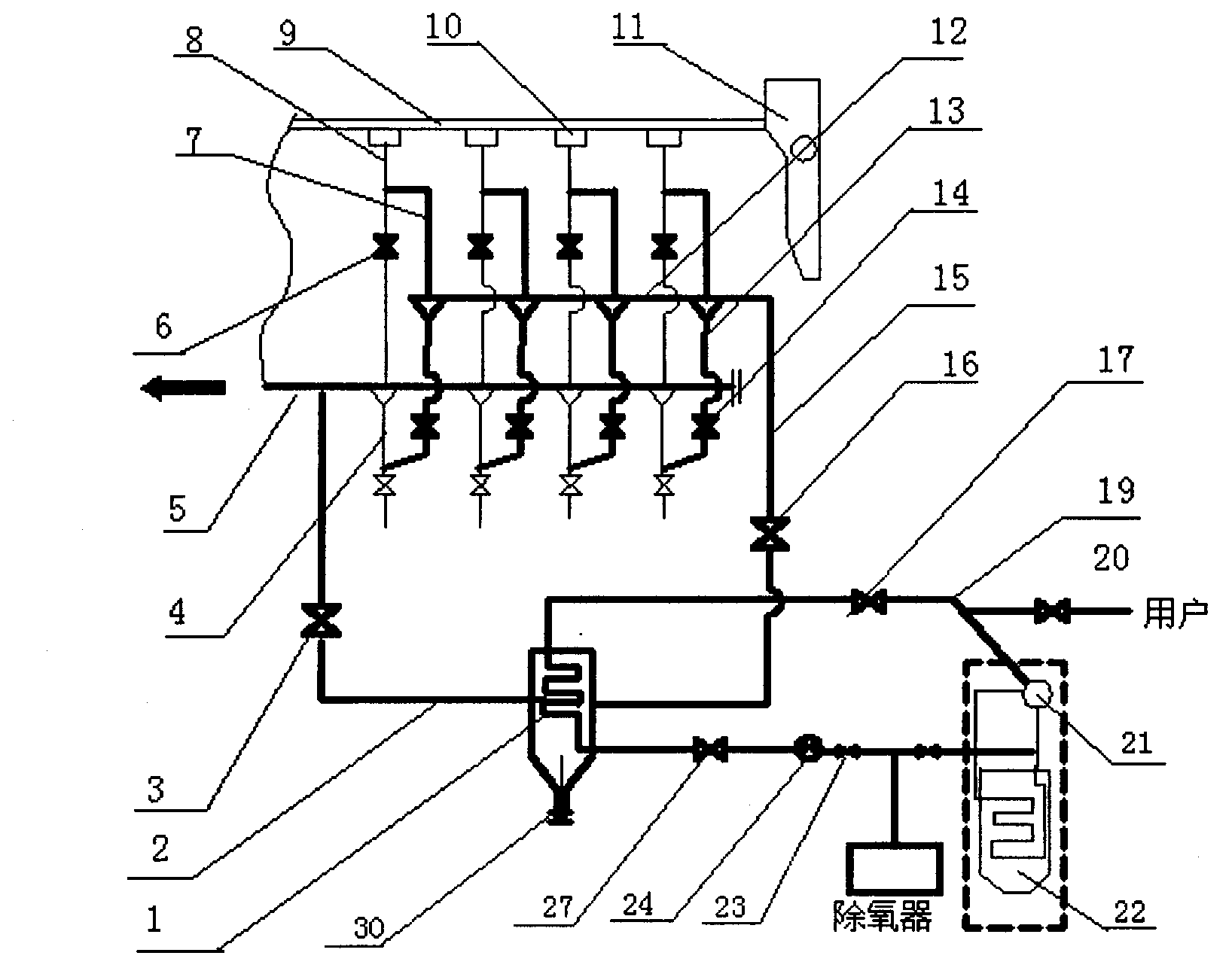
[0021] Such as figure 1 As shown, the sintering machine tail flue gas waste heat recovery system of the present invention mainly includes a heat exchanger (1), a sintering machine (9), a tail wind box (10) of a sintering machine, and a smoke exhaust of the tail wind box (10) of the sintering machine. Branch pipe (8), bypass smoke exhaust branch pipe (7) of machine tail wind box (10), bypass smoke exhaust main pipe (12), smoke exhaust branch pipe control valve (6) of machine tail wind box (10), large sintering machine Flue (5), large flue ash discharge device (4); the selected heat exchanger (1) is a shell-and-tube heat exchanger. For flue gas, the steel pipe of the heat exchanger (1) is equipped with a water inlet port and a water outlet port, and the box body of the heat exchanger (1) is equipped with an air inlet port and an air outlet port; On the four smoke exhaust branch pipes (8) between the four machine tail bellows (10) and the large flue (5), press four smoke exhaust...

Embodiment 2

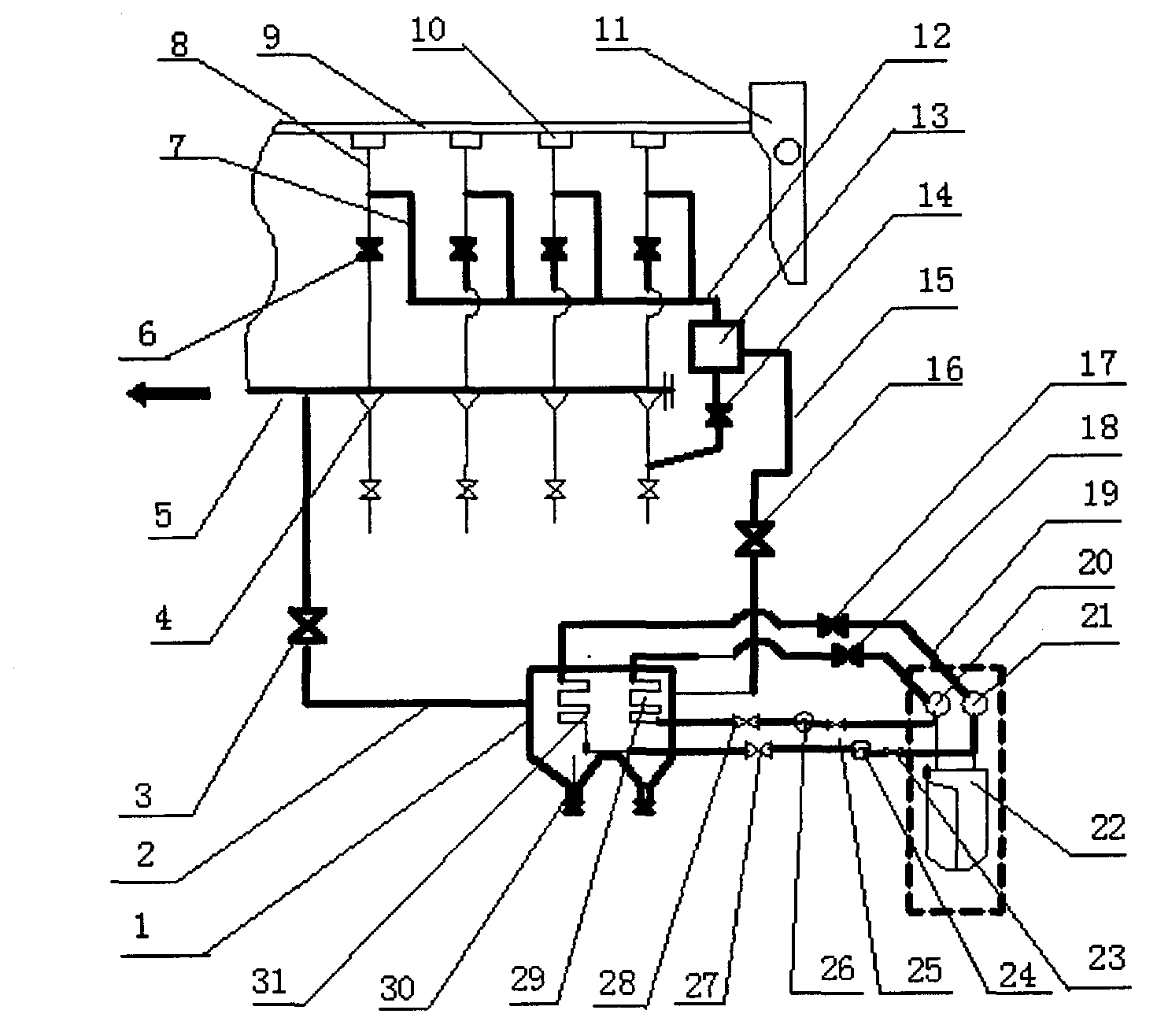
[0024] Such as figure 2As shown, the sintering machine tail flue gas waste heat recovery system of the present invention mainly includes a heat exchanger (1), a sintering machine (9), a tail wind box (10) of a sintering machine, and a smoke exhaust of the tail wind box (10) of the sintering machine. Branch pipe (8), bypass smoke exhaust branch pipe (7) of machine tail wind box (10), bypass smoke exhaust main pipe (12), smoke exhaust branch pipe control valve (6) of machine tail wind box (10), large sintering machine The flue (5), the large flue ash discharge device (4); the selected heat exchanger (1) is a double-temperature shell-and-tube heat exchanger, and the heat exchanger (1) is equipped with a high-temperature heat exchange device (29 ), the dual-temperature heat exchanger of the low-temperature heat exchange device (31), water flows inside the steel pipe in the heat exchanger (1) box, and flue gas flows outside the steel pipe, and the low-temperature heat exchange dev...


PUM


Abstract

The invention discloses a flue gas waste heat recovery system of a sintering machine tail, which is characterized in that control valves and bypass smoke exhausting branch pipes are mounted on smoke exhausting branch pipes between bellows of the sintering machine tail and a main flue; a bypass smoke exhausting header pipe is mounted on the main flue side of the sintering machine tail, and connected with the smoke exhausting branch pipes; a heat exchanger is mounted between the bypass smoke exhausting header pipe and the main flue; a water inlet pipe and a steam outlet pipe are mounted on the heat exchanger, and connected with a waste heat boiler; and flue gas heat of the sintering machine tail is recovered by the heat exchanger. According to the flue gas waste heat recovery system, since the flue gas amount from the bellows of the sintering machine tail to the heat exchanger is controlled, the flue gas heat of the sintering machine tail can be recovered sufficiently, the minimum temperature of the flue gas of the main flue is ensured, and the dewing of the flue gas is avoided. The waste heat recovery system is simple in structure and to control, and low in investment and operating cost, and is applicable to the existing sintering system and a new system.

Description

technical field [0001] The invention relates to the field of recovery and utilization of waste heat of sintering process, in particular to a method and equipment for efficiently recovering waste heat of flue gas in tail wind box of sintering machine used in sintering process of iron and steel enterprises. Background technique [0002] In the process of iron and steel production, the energy consumption of the sintering process accounts for about 12% of the total energy consumption, ranking second only to the iron-making process. In the total energy consumption of the sintering process, the energy contained in the flue gas in the large tail flue of the sintering machine accounts for about 14% to 24% of the total energy consumption of the sintering process. Because the flue gas in the large flue at the tail of the sintering machine contains a large amount of sulfur dioxide, the heat of this part of the flue gas has not been effectively utilized at present. The existing patent ...

Claims


Application Information

Patent Timeline
Patent Type & Authority Applications(China)
IPC IPC(8): F27D17/00
CPCY02P10/25Y02P80/15
Inventor 孙慕文
Owner 孙慕文
Why Eureka
Try Eureka