Non-inductive capacitor

A capacitor, non-inductive technology, applied in the direction of fixed capacitor terminal, fixed capacitor shell/package, fixed capacitor components, etc., can solve the problem of large contact resistance between the gold spray layer and the core, easy to interfere with the use of other components, and capacitor life. It can achieve the effect of excellent high-frequency performance, long service life and reasonable structure design.

Active Publication Date: 2013-10-02
WUXI HONGGUANG CAPACITOR
View PDF6 Cites 5 Cited by
  • Summary
  • Abstract
  • Description
  • Claims
  • Application Information

AI Technical Summary

Problems solved by technology

The above-mentioned capacitors can play a good role in energy storage, filtering and changing the torque of the motor in ordinary household equipment, but the inductance is too large, and it is easy to interfere with the use of other components in some equipment that requires high charging and discharging characteristics, and spray The contact resistance between the gold layer and the core is too large, resulting in high loss, which can only be used in electrical equipment with low frequency, and the life of the capacitor is not high

Method used


Image

  • Non-inductive capacitor

Examples


Embodiment Construction

[0011] The present invention will be further described below in conjunction with specific drawings.

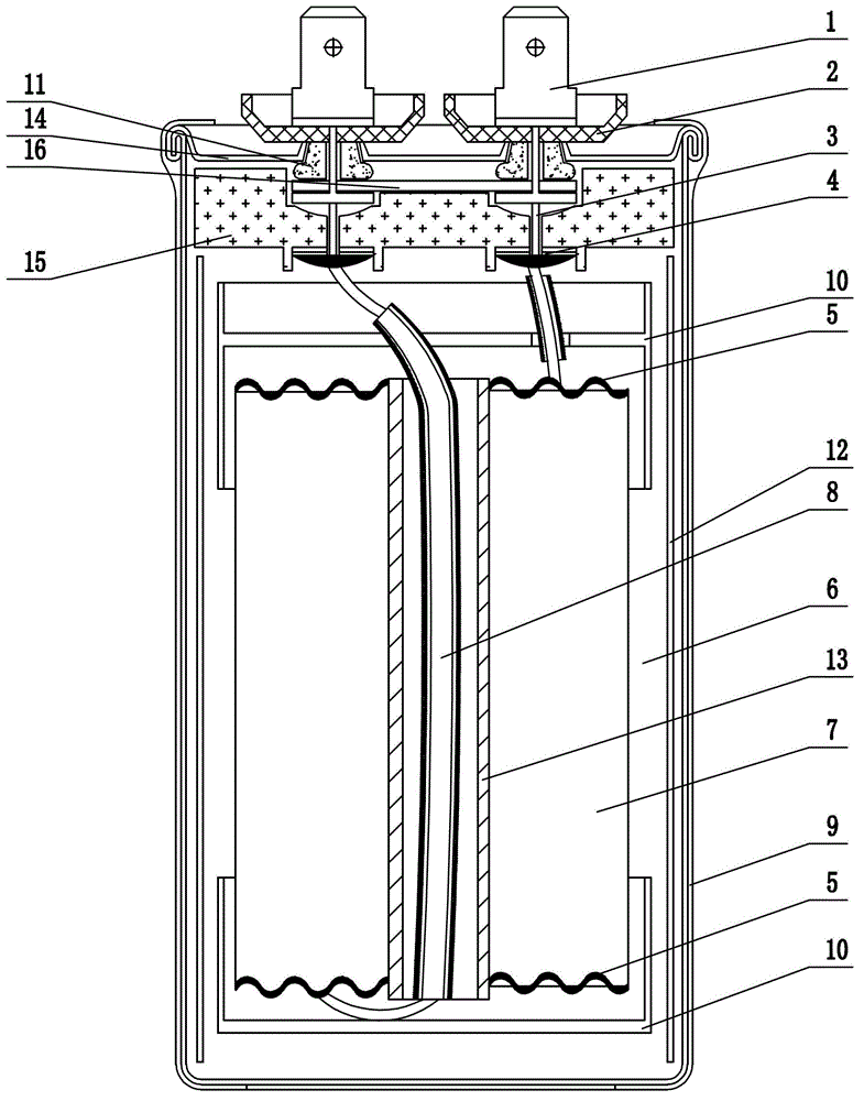
[0012] Such as figure 1 As shown: the non-inductive capacitor includes solder tab 1, plastic sheath 2, solid rivet 3, copper foil 4, zinc layer 5, filler 6, capacitive element 7, lead wire 8, aluminum shell 9, plastic sleeve 10, sealing ring 11. Film body 12, mandrel 13, explosion-proof end cap 14, explosion-proof plate 15, fixed bridge 16, etc.

[0013] Such as figure 1 As shown, the present invention comprises an aluminum casing 9 and a capacitive element 7 packaged in the aluminum casing 9, a thin film body 12 is provided between the aluminum casing 9 and the capacitive element 7, and a lead wire 8 is arranged in a mandrel 13 in the middle of the capacitive element 7 , the upper and lower ends of the capacitive element 7 are respectively provided with plastic sleeves 10; the upper end of the aluminum casing 9 is provided with an explosion-proof end cap 14, and the edge of...


PUM


Abstract

The invention relates to a non-inductive capacitor. The non-inductive capacitor comprises an aluminum housing and a capacity element, wherein film bodies are arranged between the aluminum housing and the capacity element; a lead wire is arranged in a core rod in the middle of the capacity element; an anti-explosion end cap is arranged at the upper end of the aluminum housing; the edge of the anti-explosion end cap is sealed along the aluminum housing in a tight curling manner; soldering lugs are arranged on the outer side of the anti-explosion end cap and are sealed by plastic sheaths; an anti-explosion piece is arranged on the inner side of the anti-explosion end cap; a fixed bridge is arranged between the anti-explosion piece and the anti-explosion end cap; copper foils are arranged on the lower side of the anti-explosion piece; solid rivets penetrate through the anti-explosion piece; one ends of the solid rivets are in spot welding with the upper ends of the copper foils; the other ends of the solid rivets penetrate through the fixed bridge and the anti-explosion end cap; the lower end of one copper foil is welded with the upper end of the lead wire. The non-inductive capacitor is characterized in that the upper and lower ends of the capacity element take the shape of a sinusoidal wave respectively; the edges of the upper and lower ends of the capacity element are sprayed with zinc coatings. According to the non-inductive capacitor, the contact areas of the capacity element and the zinc coatings can be enlarged; an equivalent series resistance is reduced; the heating is reduced; the high frequency performance is more excellent; the service life is longer.

Description

technical field [0001] The invention relates to a non-inductive capacitor, in particular to a non-inductive capacitor which can be used in high-frequency equipment. Background technique [0002] For the safe use of household appliances, aviation equipment and some high-precision instruments and equipment, such as solar inverter equipment, wind power generation equipment, and capacitors used in electric vehicles, non-inductive capacitors are required. Existing non-inductive capacitors have various structures. For example, patent application 201010212579 discloses a metallized film capacitor, which includes a shell and a capacitor core located in the shell. It is characterized in that the upper end of the shell is provided with a cover. The cover is covered with an epoxy resin layer and forms a sealed body together with the outer shell. Castor oil is placed between the capacitor core and the outer shell in the sealed body, and the lower part of the lead terminal is electricall...

Claims


Application Information

Patent Timeline
Patent Type & Authority Applications(China)
IPC IPC(8): H01G4/224H01G4/228H01G4/002
Inventor 周定毅匡永正赵志明
Owner WUXI HONGGUANG CAPACITOR
Why Eureka
Try Eureka