Electromagnetic system energy-saving device with compensation functions

An electromagnetic system and energy-saving device technology, applied in circuits, relays, electrical components, etc., can solve the problems of electromagnetic coil temperature rise, poor stability, etc., and achieve the effect of gentle suppression of voltage changes

Active Publication Date: 2013-10-09
浙江中凯科技股份有限公司
View PDF8 Cites 0 Cited by
  • Summary
  • Abstract
  • Description
  • Claims
  • Application Information

AI Technical Summary

Problems solved by technology

[0006] The technical problem to be solved by the present invention is the poor stability of the electromagnetic coil current and the high temperature rise of the electromagnetic coil caused by the energy-saving device of the electromagnetic system in the prior art when the power supply voltage changes greatly. Energy-saving device for electromagnetic systems with voltage compensation function and temperature compensation function

Method used


Image

  • Electromagnetic system energy-saving device with compensation functions
  • Electromagnetic system energy-saving device with compensation functions
  • Electromagnetic system energy-saving device with compensation functions

Examples


Embodiment 1

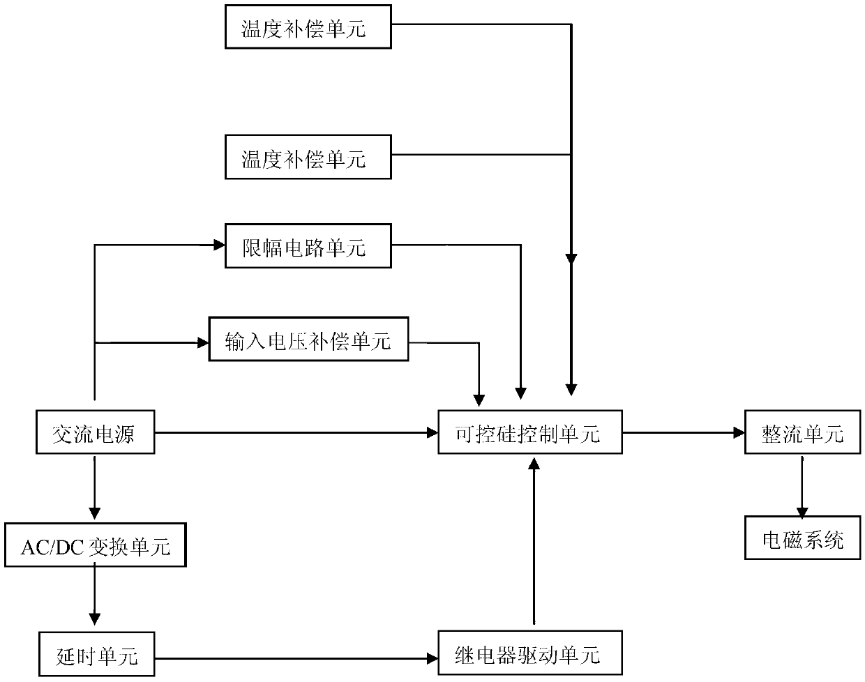
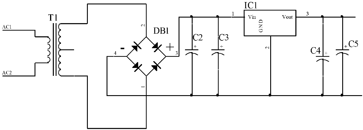
[0046] see figure 1 Shown is a block diagram of the circuit structure of an energy-saving device for an electromagnetic system according to an embodiment of the present invention. As an energy-saving device according to an embodiment of the present invention, it includes: a thyristor control unit whose input terminal is connected to an AC input power supply for adjusting the adjustable The conduction angle of the silicon controlled rectifier; the rectifier unit, the input end of which is connected to the output end of the thyristor control unit, is used to adjust the alternating current to a pulsating direct current and output it, and the output end of the rectifier unit constitutes the output end of the energy-saving device, and the output DC current to the electromagnetic coil of the electromagnetic system; AC / DC conversion unit, whose input terminal is connected to the AC input power supply, used to convert AC power into DC output as the working power supply of related circu...

Embodiment 2

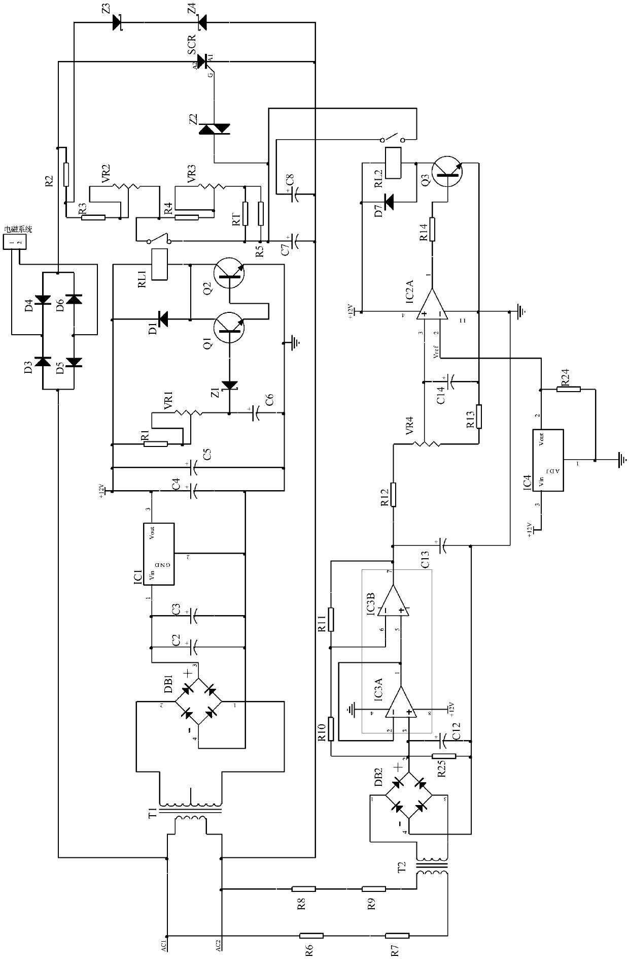
[0048] Such as figure 2 It is the circuit diagram of the energy-saving device in the first embodiment of the present invention; the energy-saving device in the first embodiment of the present invention also includes a limiter unit, which chops the power supply to make the input voltage of the thyristor control unit constant, thereby ensuring the absorption The combined voltage and holding voltage are constant and stable; it also includes a temperature compensation unit (RT), the negative temperature coefficient thermistor is placed on the surface of the electromagnetic coil, and the circuit is connected to the trigger pulse forming circuit in the thyristor control unit On the resistance of the capacitor charging circuit, when the temperature of the electromagnetic coil changes, the resistance of the thermistor changes to keep the voltage constant and achieve the stability of the electromagnetic system.

Embodiment 3

[0050] The input voltage compensation unit of the first embodiment of the present invention, such as Figure 10 As shown, the input voltage compensation unit includes: resistor R6 ~ resistor R14, resistor R24, resistor R25, current-type voltage transformer T2, bridge rectifier DB2, capacitor C8, capacitor C12 ~ capacitor C14, integrated operational amplifiers IC2A and IC3 , integrated reference power supply IC4, relay RL2, triode Q3, diode D7, and variable resistor VR4; the primary side of the resistors R6 to R9 and the transformer T2 constitute the input terminal of the input voltage compensation unit, and the resistors R6 and R7 are sequentially After being connected in series, one end is connected to the AC1 end of the AC power supply, and the other end is connected to one end of the primary side of the current-type voltage transformer T2. The resistors R8 and R9 are connected in series in sequence. The other end of the primary side of the type voltage transformer T2, the s...


PUM


Abstract

The invention relates to an electromagnetic system energy-saving device with compensation functions. The energy-saving device comprises an alternating current input power supply, a controllable silicon control unit, a rectification unit, an AC / DC converting unit, a delaying unit, a relay driving unit, an input voltage compensation unit, an amplitude limiting unit and a temperature compensation unit. An absorbing and retention state can be stable before changing of voltages, the requirements for wide-range voltage input are met, the technical problems that in the prior art, stability is bad, and an electromagnetic coil is too high in temperature rising caused by non-constant electromagnetic coil currents when an electromagnetic system energy-saving device is large in voltage changing are solved, and the electromagnetic system energy-saving device has the voltage compensation function and the temperature compensation function.

Description

technical field [0001] The invention relates to the technical field of low-voltage electrical appliances, in particular to an energy-saving device for an electromagnetic system with a compensation function. Background technique [0002] AC contactors are widely used in power breaking and control circuits, which use the main contacts to open and close the circuit, and use the auxiliary contacts to execute control commands. The main contacts generally only have normally open contacts, while the auxiliary contacts often have two pairs of contacts with normally open and normally closed functions. The AC contactor mainly consists of four parts: (1) Electromagnetic system, including the attraction coil, moving iron core and static iron core; (2) contact system, including three sets of main contacts and one to two sets of normally open and normally closed auxiliary contacts, which are linked together with the moving iron core; (3) arc extinguishing device, general capacity Larger ...

Claims


Application Information

Patent Timeline
IPC IPC(8): H01H47/02
Inventor 黄世泽朱谅仇丁辉杨佰传屠瑜权
Owner 浙江中凯科技股份有限公司
Why Eureka
Try Eureka