Polysilicon directional solidification device

A technology of directional solidification and polysilicon, applied in the direction of silicon compounds, inorganic chemistry, non-metallic elements, etc., can solve the problems of increasing energy consumption, failure to purify polysilicon, and affecting the effect of directional solidification and impurity removal, and achieve short heating time and cooling speed Can control and realize the effect of directional solidification

Inactive Publication Date: 2013-10-16
QINGDAO NEW ENERGY SOLUTIONS
View PDF2 Cites 4 Cited by
  • Summary
  • Abstract
  • Description
  • Claims
  • Application Information

AI Technical Summary

Problems solved by technology

[0005] At present, the directional solidification technology basically uses the pull-down method of the quartz crucible to directional solidify the polysilicon. The pull-down is to gradually pull the quartz crucible out of the thermal field area. Since the height of the current insulation sleeve is basically the same as that of the quartz crucible, the part of the pulled-down quartz crucible is exposed. In the furnace body, a large amount of heat will be dissipated from the surroundings, causing the temperature of the outer wall of the quartz crucible in the pull-down part to be lower than the central temperature. In this way, polysilicon will grow along the side wall toward the center, causing the metallic impurities in the polysilicon to move from the surrounding to the center. Enrichment will affect the effect of directional solidification and impurity removal in light cases, and lead to the failure of qualitative solidification to purify polysilicon in severe cases
In addition, the directional solidification technology basically adopts the design of the water-cooled copper plate on the upper part of the ingot pulling mechanism to cool the bottom of the quartz crucible with circulating water, so that the silicon melt can be directional solidified. The cold source of this method exists in the whole process of smelting. , this method will take away a large amount of heat energy, thereby increasing energy consumption

Method used


Image

  • Polysilicon directional solidification device
  • Polysilicon directional solidification device
  • Polysilicon directional solidification device

Examples


Embodiment 1

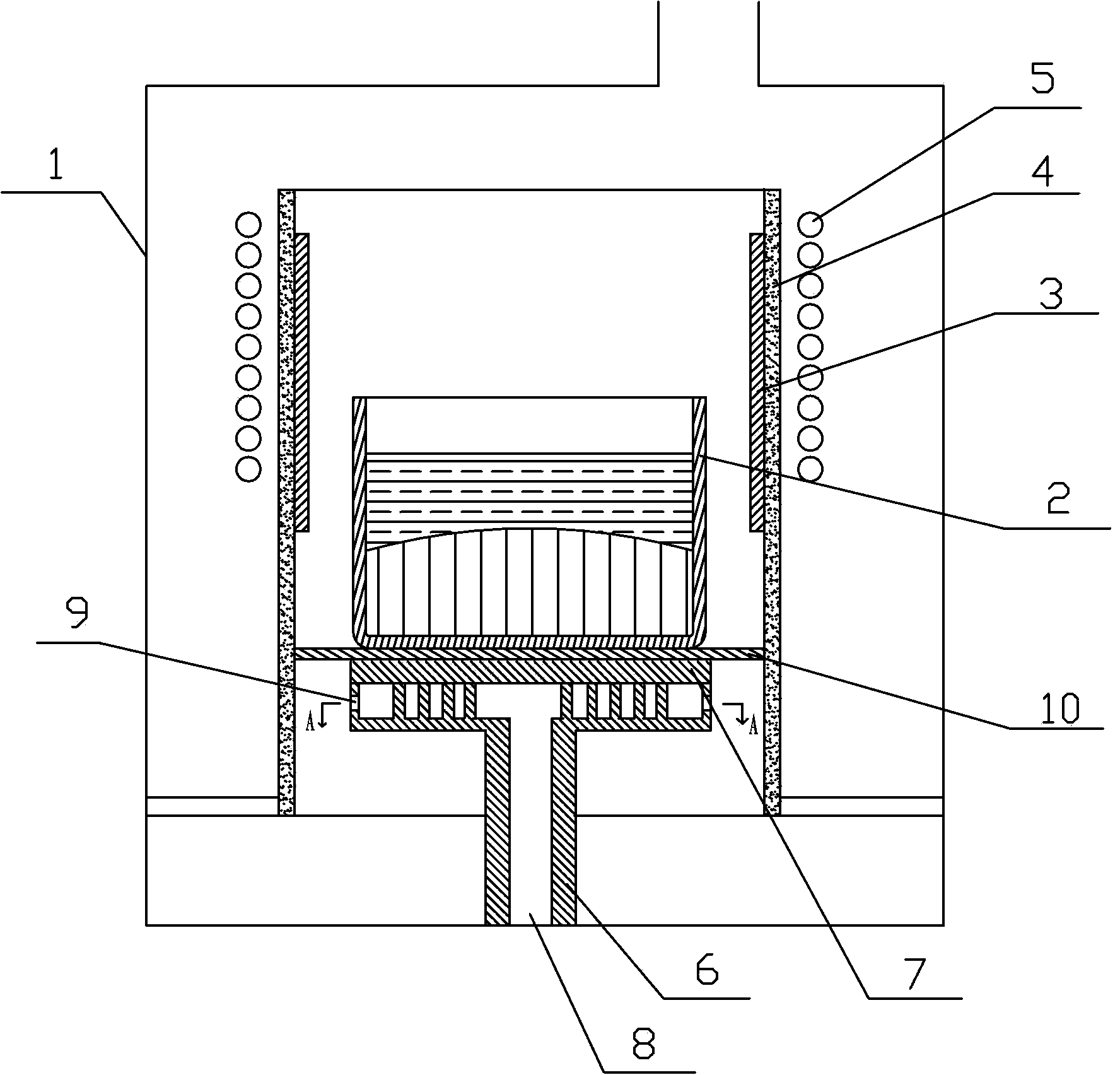
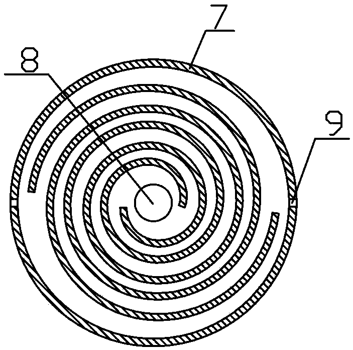
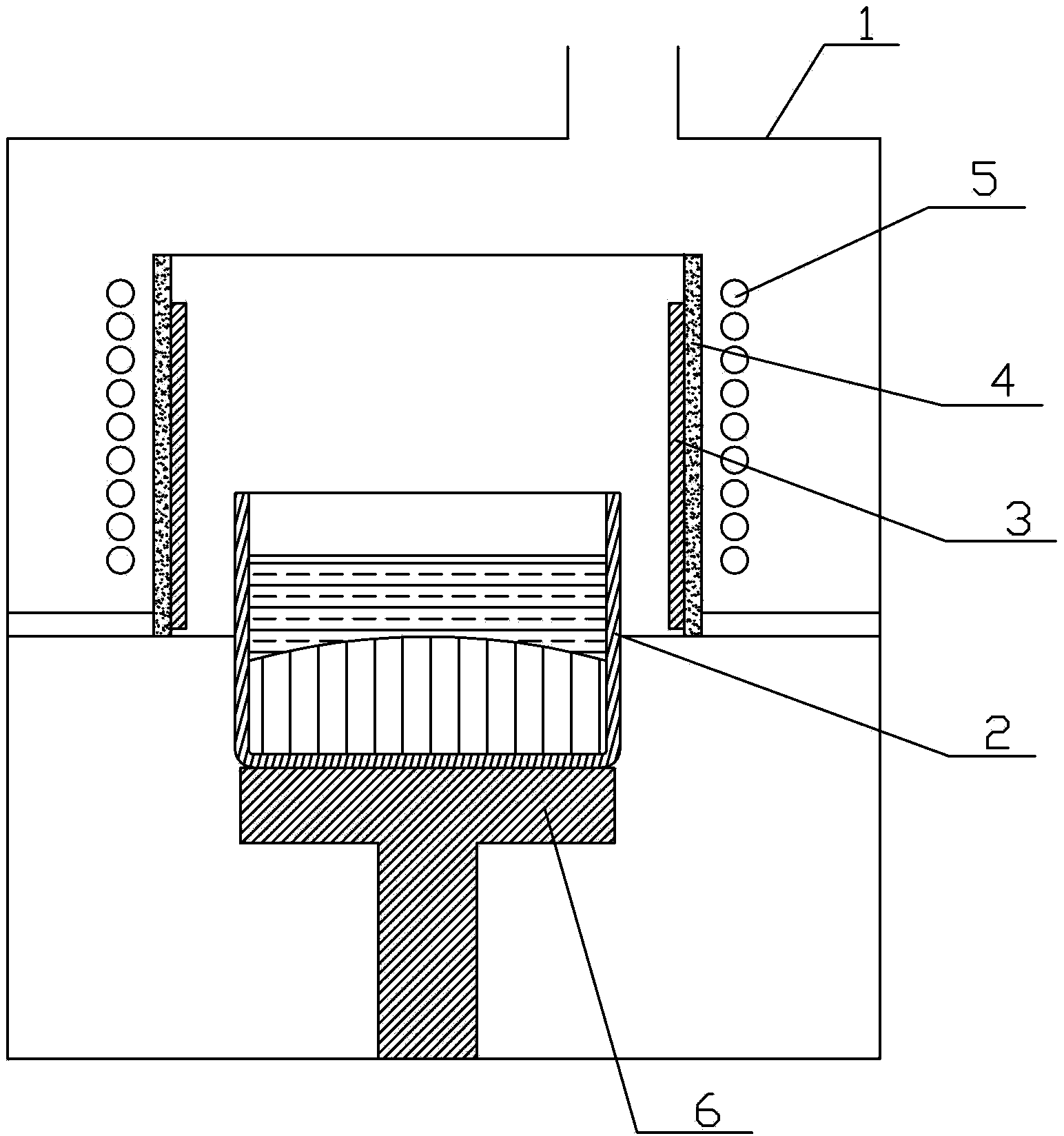
[0026] Such as Figure 1 ~ Figure 3 As shown, a polysilicon directional solidification device includes a furnace body 1, a quartz crucible 2 is placed in the furnace body 1, and the outer wall of the quartz crucible 2 is surrounded by a graphite heating element 3, a thermal insulation sleeve 4 and an induction coil 5 sequentially from the inside to the outside. The bottom of the quartz crucible 2 is provided with an ingot pulling mechanism 6 connected to the bottom of the furnace body 1. The height of the heat preservation sleeve 4 is twice the height of the quartz crucible 2. The upper part of the ingot pulling mechanism 6 is a graphite spiral plate 7, and the graphite spiral plate 7 The built-in spiral channel communicates with the air inlet 8 of the ingot pulling mechanism 6 , and there are air outlets 9 on both side edges of the graphite spiral plate 7 .

[0027] A graphite supporting plate 10 is arranged between the quartz crucible 2 and the ingot pulling mechanism 6 , an...


PUM


Abstract

The invention relates to the field of polysilicon purification, in particular to a polysilicon directional solidification device which comprises a furnace body, a quartz crucible is placed in the furnace, a graphite heating unit, an insulating sleeve and a induction coil are arranged on the outer wall of the quartz crucible from inside to outside in sequence in a surrounding manner, an ingot mechanism communicated with the bottom of the furnace body is arranged at the bottom of the quartz crucible, the height of the insulating sleeve is 1.5 to 2 time higher of that of the quartz crucible, a graphite spiral plate is arranged at the upper part of the ingot mechanism, a spiral channel built in the graphite spiral plate is communicated with the inlet of the ingot mechanism, and outlets are formed in the edge of the two sides of the graphite spiral plate. According to the device, thermal radiation of the sidewall of the quartz crucible generated in the pulling process can be better intercepted, thermal radiation of the sidewall of the quartz crucible is effectively decreased, and the directional solidification effect is better than conventional solidification method. The device is short in warming up time, small in insulating energy consumption, controllable in cooling speed, the crystal growth is better in cooling method when compared with conventional mode, and can better realize directional solidification effect.

Description

technical field [0001] The invention belongs to the field of polysilicon purification, and in particular relates to a polysilicon directional solidification device. Background technique [0002] At present, my country has become the world's largest energy production and consumption country, but the per capita energy consumption level is still very low. With the continuous development of the economy and society, my country's energy demand will continue to grow. In response to the current energy shortage, countries around the world are thinking deeply, and are working hard to improve energy efficiency, promote the development and application of renewable energy, and reduce the impact on energy consumption. Reliance on imported oil to enhance energy security. [0003] As one of the important development directions of renewable energy, solar photovoltaic power generation has developed rapidly in recent years, and its proportion is increasing. According to the Medium and Long-te...

Claims


Application Information

Patent Timeline
Patent Type & Authority Applications(China)
IPC IPC(8): C01B33/037
Inventor 谭毅温书涛陈磊袁涛
Owner QINGDAO NEW ENERGY SOLUTIONS
Why Eureka
Try Eureka