Linear double-acting thermo-acoustic power generation system

A power generation system, linear technology, applied in the direction of machines/engines, mechanical equipment, mechanisms that generate mechanical power, etc.

Active Publication Date: 2013-10-16
TECHNICAL INST OF PHYSICS & CHEMISTRY - CHINESE ACAD OF SCI
View PDF5 Cites 18 Cited by
  • Summary
  • Abstract
  • Description
  • Claims
  • Application Information

AI Technical Summary

Problems solved by technology

[0008] The disadvantage of this structure is that to achieve a larger power output, it is necessary to increase the number of linear motors and thermoacoustic engines, but the phase difference of the gas volume flow rate at both ends of the thermoacoustic engine is closely related to the number of units connected in series to the circuit. If the number is further increased, the regenerator of the thermoacoustic engine cannot work in a suitable traveling wave phase, and cannot generate large sound power for power generation and obtain ideal efficiency

Method used


Image

  • Linear double-acting thermo-acoustic power generation system
  • Linear double-acting thermo-acoustic power generation system
  • Linear double-acting thermo-acoustic power generation system

Examples


Embodiment 1

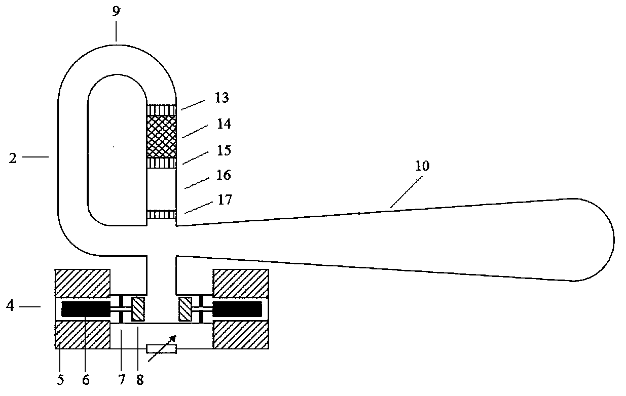
[0073] Figure 4 It is a schematic structural diagram of a linear double-acting thermoacoustic power generation system (Example 1) of the present invention. like Figure 4 As shown, the linear double-acting thermoacoustic power generation system of the present embodiment 1 consists of the first thermoacoustic engine (also known as the first thermoacoustic converter) connected in series between the linear compressor 1 and the linear generator 4 device) 2-1, a linear double-acting generator 3 and a second thermoacoustic engine (also known as a second thermoacoustic converter) 2-2;

[0074] The linear compressor 1 is located at the starting end of the system, which consists of a first compression piston 8, a compressor mover 6 connected to the first compression piston 8, a first leaf spring 7 for fixing the compressor mover 6 and Composed of a compressor stator coil 5 wound around the periphery of the compressor mover 6;

[0075] Both the first thermoacoustic engine 2-1 and th...

Embodiment 2

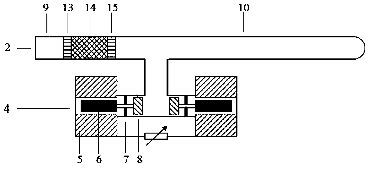
[0082] Figure 5 It is a schematic structural diagram of a linear double-acting Stirling power generation system (Example 2) of the present invention. like Figure 5 As shown, the linear double-acting Stirling power generation system of the present embodiment 2 consists of a linear compressor 1 sequentially connected in series between the linear compressor 1 and the linear generator 4, the first Stirling engine 2 -1. The linear double-acting generator 3, the second Stirling engine 2-2 and the linear generator 4 are composed.

[0083] The linear compressor 1 works at the beginning of the system, and the linear generator 4 works at the end of the system; the linear compressor 1 of this embodiment has the same structure as the linear compressor 1 of Embodiment 1; The linear generator 4 and the linear double-acting generator 3 are slightly different from those in Embodiment 1. The difference is that the linear generator 4 and the linear double-acting generator are used to genera...

Embodiment 3

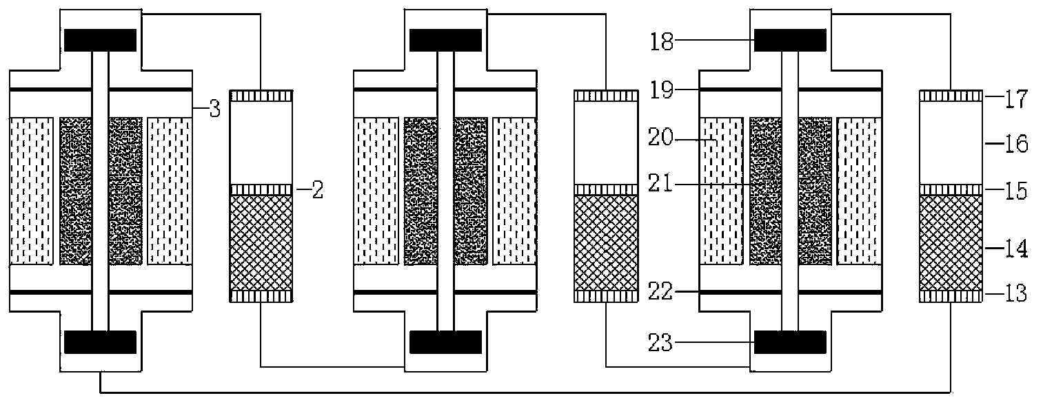
[0086] Figure 6 It is a structural schematic diagram of a novel linear double-acting thermoacoustic generator system (Example 3) of the present invention. like Figure 6 As shown, the linear double-acting thermoacoustic power generation system of Embodiment 3 consists of the first thermoacoustic engine 2-1, the first linear The double-acting generator 3-1 is composed of the second thermoacoustic engine 2-2, the second linear double-acting generator 3-2 and the third thermoacoustic engine 2-3.

[0087] The linear compressor 1 works at the beginning of the system, and the linear generator 4 works at the end of the system; the linear compressor 1 of this embodiment has the same structure as the linear compressor 1 of Embodiment 1; Linear generator 4 is identical in structure with the linear generator 4 of embodiment 1;

[0088] The first thermoacoustic engine 2-1, the second thermoacoustic engine 2-2 and the third thermoacoustic engine 2-3 of this embodiment are all composed ...


PUM


Abstract

The invention provides a linear double-acting thermo-acoustic power generation system. The linear double-acting thermo-acoustic power generation system is composed of N thermo-acoustic engines and N-1 linear double-acting generators, wherein the thermo-acoustic engines and the linear double-acting generators are sequentially connected in series between the linear compressor and a linear generator at intervals. The linear compressor is arranged at the initial end of the system and the linear generator is arranged at the tail end of the system. The linear compressor and the linear generator are both work with a single piston. Two pistons of each linear double-acting generator can work at the same time. N is a positive integer ranging from 2 to 20. A resonant tube structure is removed in the system so that the empty size of the system is greatly reduced, power density is improved, and frequency characteristics of linear motors at the two ends of the thermo-acoustic engine are adjusted to achieve required phases. The acoustic power generated by the thermo-acoustic engine is not consumed by the resonant tube, but absorbed by expansion pistons of the linear motors and a higher efficiency is obtained. In addition, a heat source of the thermo-acoustic engine can utilize low-grade energy sources such as solar energy, industrial waste gas and smoke, and the energy utilization rate is improved.

Description

technical field [0001] The invention relates to a thermoacoustic power generation system, in particular to a linear double-acting thermoacoustic power generation system. Background technique [0002] Electric energy is widely used in various fields such as power, lighting, metallurgy, chemistry, textile, communication, broadcasting, etc. It is the main driving force for the development of science and technology and the leap of the national economy, and it is an indispensable secondary energy source. Thermal power generation and nuclear power generation are the main sources of electricity in my country at present. However, thermal power generation not only consumes non-renewable resources such as coal and oil, but also may be accompanied by a large amount of pollution and waste gas; the nuclear waste of nuclear power generation will also have a greater impact on the environment, and there are safety hazards. Although solar energy, tidal energy, water energy, wind energy, geo...

Claims


Application Information

Patent Timeline
Patent Type & Authority Applications(China)
IPC IPC(8): F03G7/00
Inventor 罗二仓童欢戴巍陈燕燕吴张华胡剑英
Owner TECHNICAL INST OF PHYSICS & CHEMISTRY - CHINESE ACAD OF SCI
Why Eureka
Try Eureka