
Method for treating industrial circulating water

A technology of industrial circulating water and treatment method, which is applied in the field of controlling the growth of microorganisms in the circulating water system and preventing the production of biological slime. Reduced heat transfer efficiency and other issues, to achieve the effect of solving growth and reproduction problems, reducing the dosage of chemicals, and increasing the concentration multiple

Active Publication Date: 2013-10-30
CHINA PETROLEUM & CHEM CORP +1
View PDF12 Cites 6 Cited by
  • Summary
  • Abstract
  • Description
  • Claims
  • Application Information

AI Technical Summary

Problems solved by technology

This method can degrade the biochemical substances in the circulating water and then return the circulating water to the device area. It can control the growth and reproduction of microorganisms by limiting the substrate concentration, thereby reducing the production of biological slime, and truly solving the problem of biological problems in the circulating water system. Breeding, slime deposits lead to a decrease in the heat transfer efficiency of the heat exchanger, corrosion of equipment, blockage of cooling water tower cloth holes and grilles, etc.

Method used


Image

  • Method for treating industrial circulating water

Examples


Embodiment 1

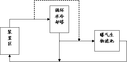
[0025] The circulating water volume of a circulating water plant is 27,000 tons / hour, the COD (chromium method, the same below) of the circulating water influent is 39.2~70mg / L, and the ammonia nitrogen is 2.2~6.9mg / L. Among them, 900 tons / hour of circulating water enters the biological aerated filter (BAF). The operating conditions of the biological aerated filter are: temperature 28°C, pH 7.5, DO 1.5mg / L. Mix the denitrification and denitrification bacteria agent with the activated sludge and add it to the biological aerated filter according to the dosage of MLSS of 1000mg / L. Biofilm formation can be seen after 20 days. At this time, according to the dosage of 100mg / L of MLSS The amount of nitrifying bacteria is added. After treatment, the ammonia nitrogen in the effluent is lower than 2mg / L, and the COD is lower than 5mg / L. The concentration ratio of the circulating water is increased from 4.5 to 5.5. After long-term use, the quality of the circulating water is basically unc...

Embodiment 2

[0027] In the circulating cooling water system of a large petrochemical refinery in China, the total amount of circulating water is 22,000 tons / hour, the control cycle concentration ratio is 2.5, the supplementary water volume is 600 tons / hour, the COD of circulating water is 60.2~79mg / L, and the ammonia nitrogen is 7.2 ~10.9mg / L. The aeration raw filter is used to partially treat the circulating cooling water behind the cooling tower, and the treated circulating water is 1100 tons / hour. First, mix the denitrifying bacteria agent into the activated sludge according to the sludge volume ratio of 0.05%, and then add the mud bacteria mixture to the biological aerated filter. Add the dosage of L to add nitrifying bacteria. The operating conditions of the biological aerated filter are: temperature: 32°C, pH: 7.8, DO: 2.0mg / L. After treatment, the ammonia nitrogen and COD in the effluent are always lower than 5mg / L, which fully meets the water quality requirements of the circulati...


PUM


Abstract

The invention relates to a method for biologically purifying industrial circulating water. The method is characterized in that a biodegradation reactor is arranged in a circulating water system; nitrobacteria and denitrifiers are taken as inocula in the biodegradation reactor; at least part of the circulating water enters the biodegradation reactor to be biologically treated; and the water from the biodegradation reactor enters the circulating water system. Compared with the prior art, the method has the advantages that the biological treatment method is adopted to treat the nutrient sources needed by microorganisms before the circulating water enters the device, so that the microorganisms brought in by the circulating water in the circulating process are difficult to survive, and then growth and reproduction of the microorganisms in the circulating water system are controlled.

Description

technical field [0001] The invention relates to a treatment method for industrial circulating water, in particular to a method for controlling the growth of microorganisms in a circulating water system and preventing the production of biological slime. Background technique [0002] The industrial circulating water system is a large water user. The circulating water is mainly used as a cooling medium and is responsible for exchanging heat for the heated material. The temperature of this part of the water is low when it enters the device, and the temperature is high when it is circulated back from the device. Therefore, it needs to be recycled when it is reused. The cooling tower of the water plant (generally there is filler in the tower) for cooling treatment. Most of the cooling towers adopt an open structure. The bottom of the tower is vented with air, and the water flows from top to bottom. In the cooling tower, the contact between water and air can reduce the water temper...

Claims


Application Information

Patent Timeline
IPC IPC(8): C02F3/30C02F3/34
Inventor 高会杰张鹏刘忠生
Owner CHINA PETROLEUM & CHEM CORP
Learn More