Fiber array coupled with VSCEL or PIN array and manufacturing method of fiber array

An optical fiber array and a manufacturing method technology, applied in the field of optical fiber arrays, can solve the problems of high production cost, unusable use, and fragile grinding surface of bare optical fiber microstrips, achieving good grinding angle consistency, reducing the consumption of raw materials, and being easy to use. The effect of mass production

Active Publication Date: 2013-11-06
WUHAN POWERISE OPTOELECTRONICSAL TECH
View PDF10 Cites 24 Cited by
  • Summary
  • Abstract
  • Description
  • Claims
  • Application Information

AI Technical Summary

Problems solved by technology

[0007] But there are some problems with the method discussed in the patent 03128028.5: In order to provide a good optical path between the FA and the VCSEL array or PIN array, this patent uses a method of shortening the cover slip so that a part of the bare optical fiber microstrip has no cover slip Blocking, avoiding the reduction of coupling efficiency caused by the light path passing through the cover
[0009] Although the patent 201110376526.6 avoids the shortcomings encountered in the patent 03128028.5, new problems have arisen: 1) Since the bare optical fiber microstrip that has been ground at 45° needs to be discharged into the new V-groove, it cannot be guaranteed during the fiber discharge process. Each fiber does not undergo a slight twist, so the angle of each 45° reflection surface of the bare fiber microstrip may be inconsistent; 2) The consistency of the protruding length of each fiber cannot be guaranteed during the fiber rearrangement process, It will cause coupling difficulties for some channels; 3) The lower end of the ground cut surface of the bare optical fiber microstrip that is ground into a 45° optical reflection surface is very fragile, and it is easy to cause damage during the re-fiber arrangement process and make it unusable; 4) It requires two 5) The V-groove after the first grinding cannot be reused, and the production of a 45° fiber array requires 2 times the raw materials, and the production cost is high
6) The method proposed in this patent uses the V-groove as the coupling base, and the V-groove should not be too thin, generally more than 1mm, otherwise it will break during the process of making the V-groove, which will cause its 45° optical reflection surface to be incompatible with the VCSEL array or The optical distance of the PIN array (150um high) is longer, about 850um, which reduces the coupling efficiency

Method used


Image

  • Fiber array coupled with VSCEL or PIN array and manufacturing method of fiber array
  • Fiber array coupled with VSCEL or PIN array and manufacturing method of fiber array
  • Fiber array coupled with VSCEL or PIN array and manufacturing method of fiber array

Examples


Embodiment Construction

[0042] The principles and features of the present invention are described below in conjunction with the accompanying drawings, and the examples given are only used to explain the present invention, and are not intended to limit the scope of the present invention.

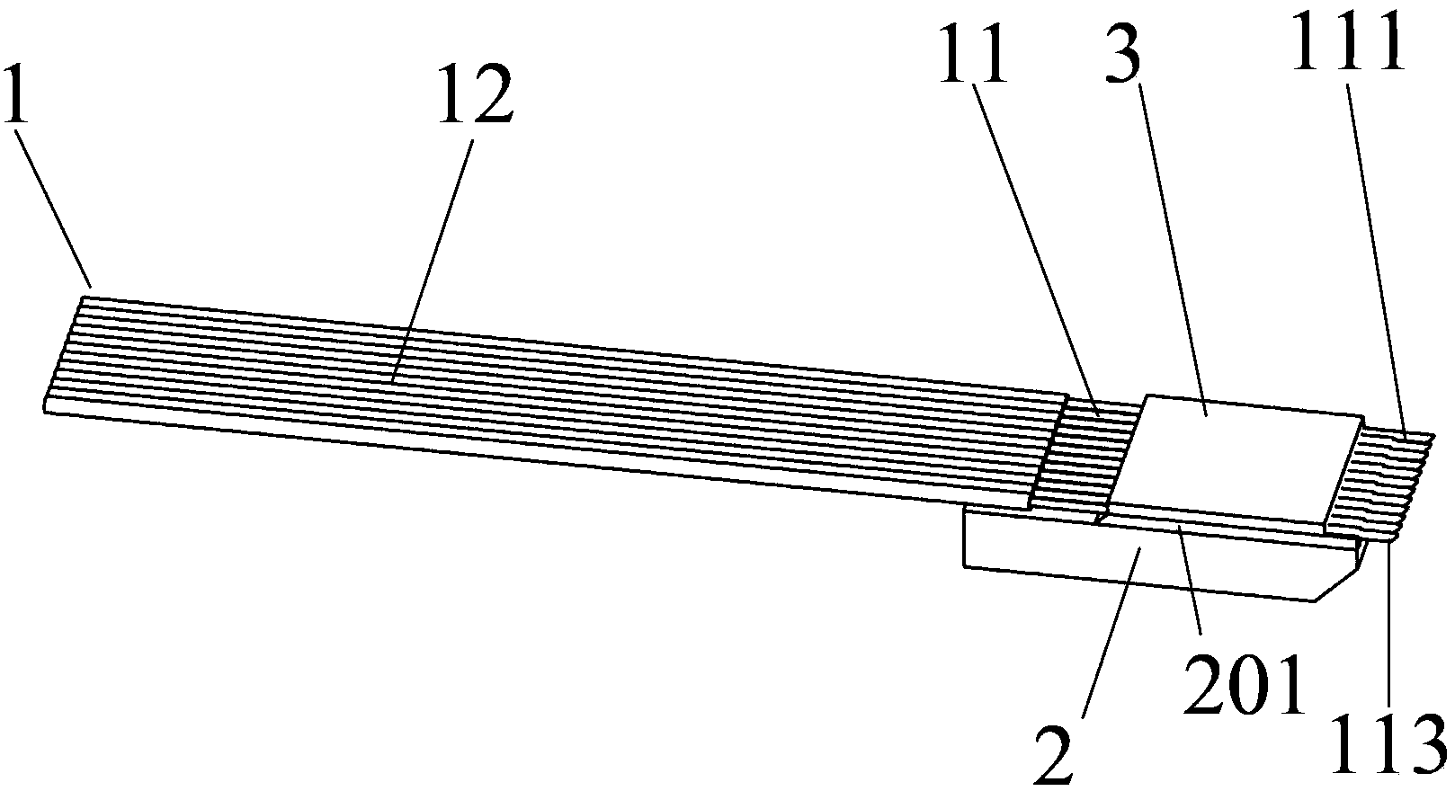
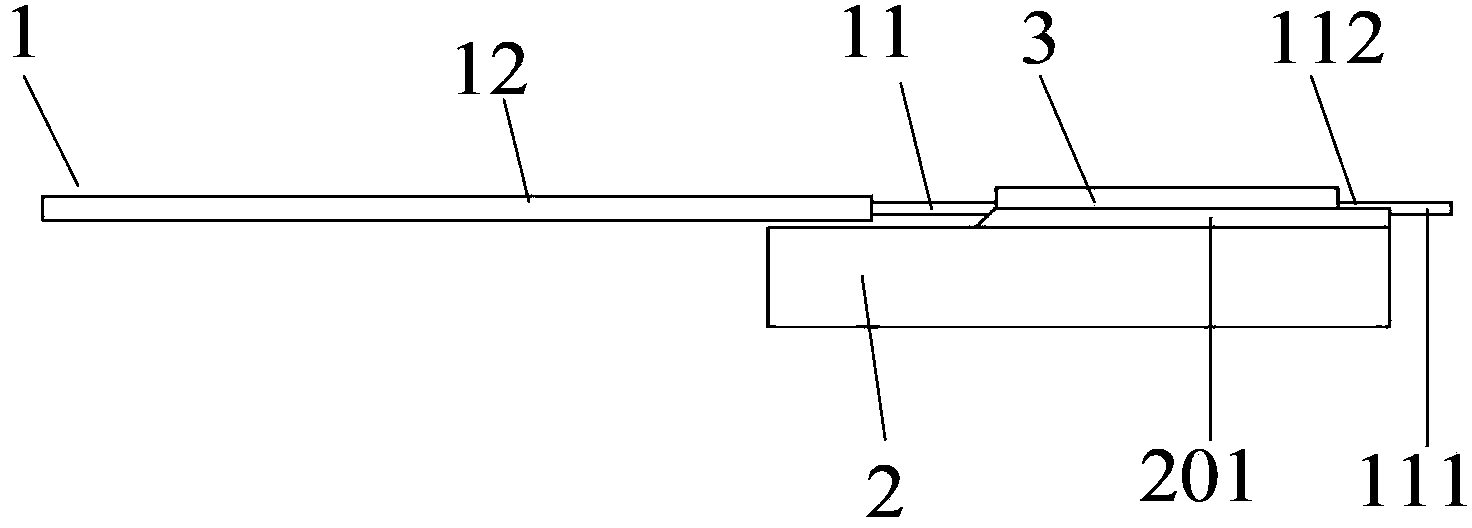
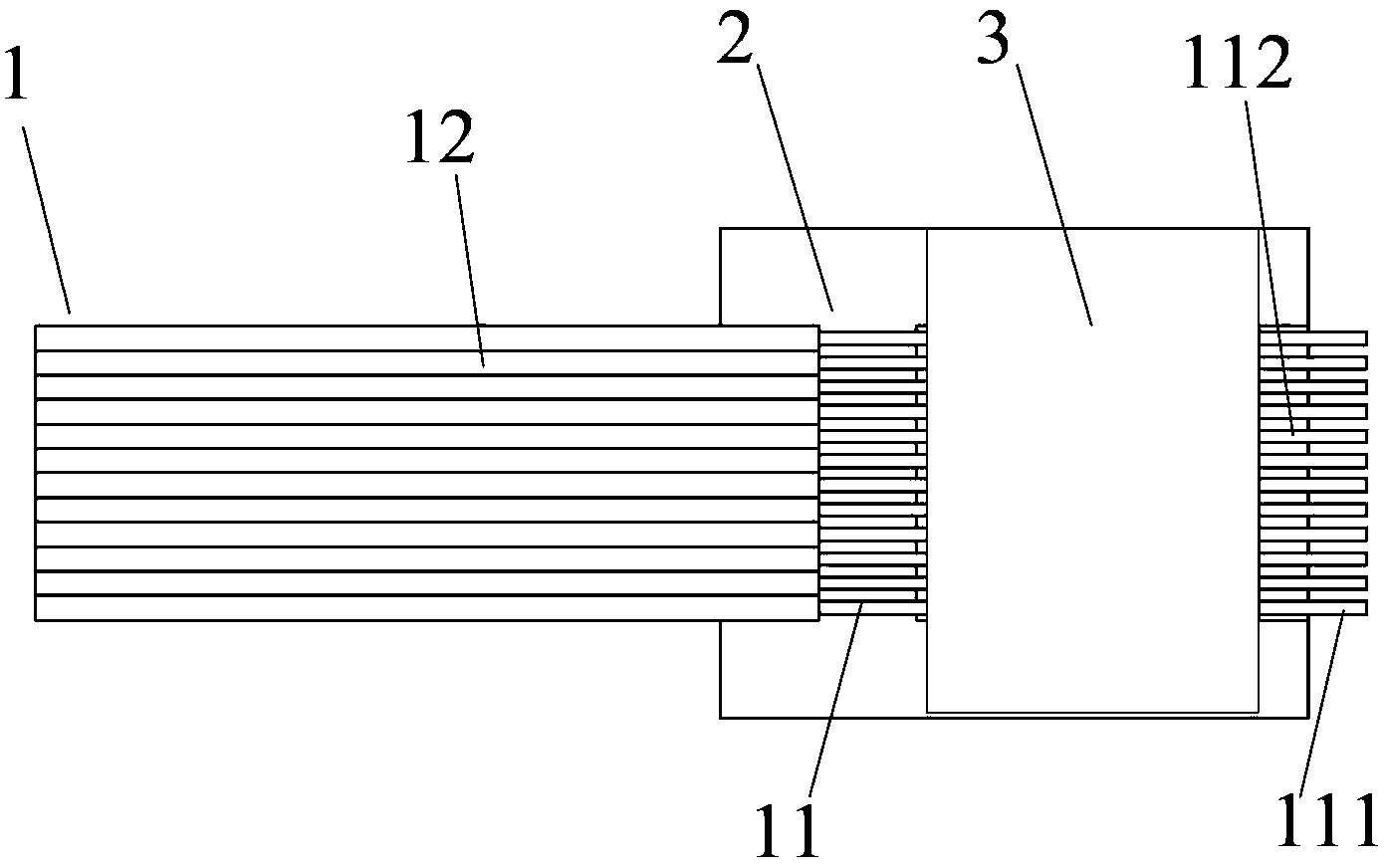
[0043] figure 1 Be used for the structural representation of the optical fiber array that the present invention is coupled with VSCEL or PIN array, as figure 1 As shown, the optical fiber array includes an optical fiber microstrip 1 , a grooved substrate 2 and a cover sheet 3 . The grooved substrate 2 and the cover 3 can be made of quartz glass, borosilicate glass or silicon material. The optical fiber microstrip 1 includes a plurality of optical fibers arranged in parallel, and an optical fiber layer is applied to the optical fiber. The optical fiber microstrip 1 includes an optical fiber microstrip layered portion 12 with an optical fiber layer applied thereto and a bare optical fiber microstrip portion 11 from w...


PUM


Abstract

The invention relates to a fiber array coupled with a VSCEL or PIN array and a manufacturing method of the fiber array. The fiber array comprises a cover slip, a carving groove substrate and a fiber micro-strip, the fiber micro-strip comprises an exposed fiber micro-strip portion without a fiber coating, a V-shaped carving groove for holding the exposed fiber micro-strip portion is formed in the carving groove substrate, the cover slip presses the groove of the exposed fiber micro-strip portion, the carving groove substrate, the cover slip and the exposed fiber micro-strip portion are fixedly connected through binding agents, the cover slip is shorter than the V-shaped carving groove, the end face of the exposed fiber micro-strip portion is an optical plane with a 45-degree oblique angle, and the optical plane faces the carving groove substrate. The coupling distance between the 45-degree optical plane of the exposed fiber micro-strip portion and the VSCEL or PIN array is controlled by the aid of the cover slip of the fiber array, the thickness of the cover slip can be customized, and high-efficiency coupling is realized. The method for manufacturing the fiber array is simple, easy to implement and low in cost.

Description

technical field [0001] The invention relates to an optical fiber array coupled with parallel optical channels in technical fields such as parallel photoelectric transceiver modules and active optical cables in optical communication technology, in particular to an optical fiber array for coupling with a VSCEL or PIN array and a manufacturing method thereof. Background technique [0002] With the rapid growth of human's demand for communication, the existing communication system is facing greater challenges. Among them, speed and energy consumption are two very critical factors. People expect greater bandwidth in less space and lower power consumption. Therefore, the research on parallel optical transceiver modules has been extensively studied. [0003] Among commonly used communication lasers such as LD lasers and VCSEL lasers, VCSEL has the advantages of high conversion efficiency and low threshold, so its power consumption is smaller than other types of lasers. The array...

Claims


Application Information

Patent Timeline
Patent Type & Authority Applications(China)
IPC IPC(8): G02B6/42
Inventor 江永胜阮景罗志祥朱志实
Owner WUHAN POWERISE OPTOELECTRONICSAL TECH
Why Eureka
Try Eureka