Biomass waste hydrothermal processing method and system thereof
A biomass waste and hydrothermal treatment technology, applied in the pyrolysis treatment of sludge, the removal of solid waste, etc., can solve the problem of high energy consumption, achieve the effect of low labor intensity, high work efficiency, and improve the level of resource utilization
- Summary
- Abstract
- Description
- Claims
- Application Information
AI Technical Summary
Problems solved by technology
Method used
Image

Examples
Embodiment 1
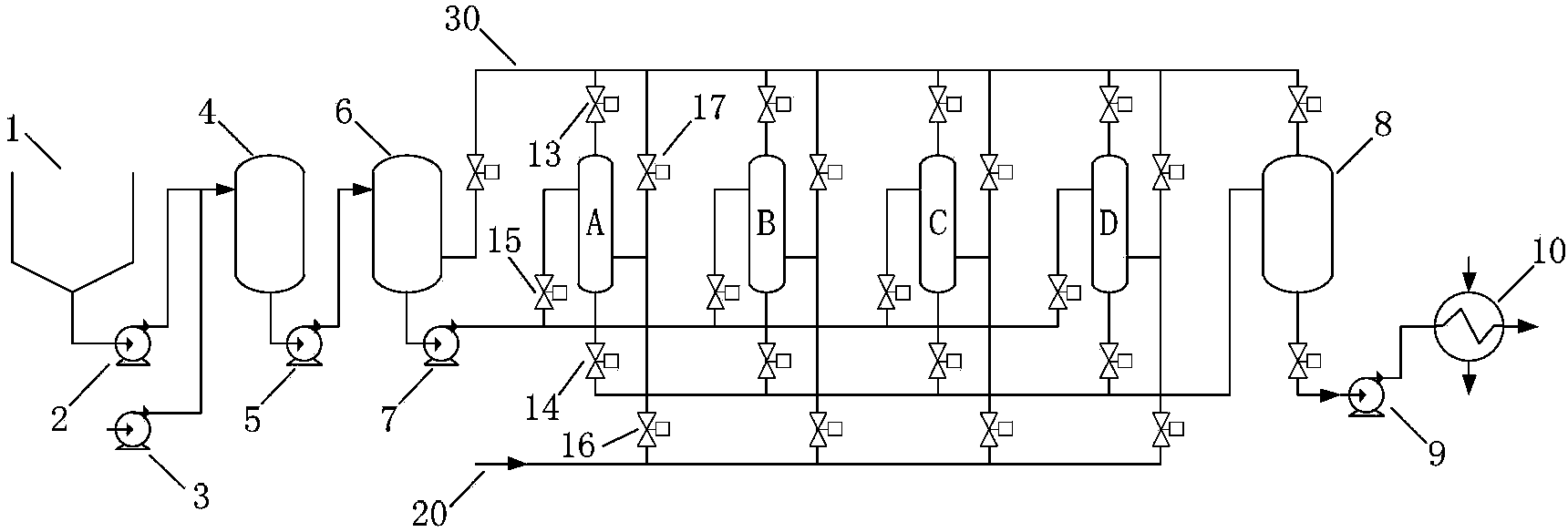
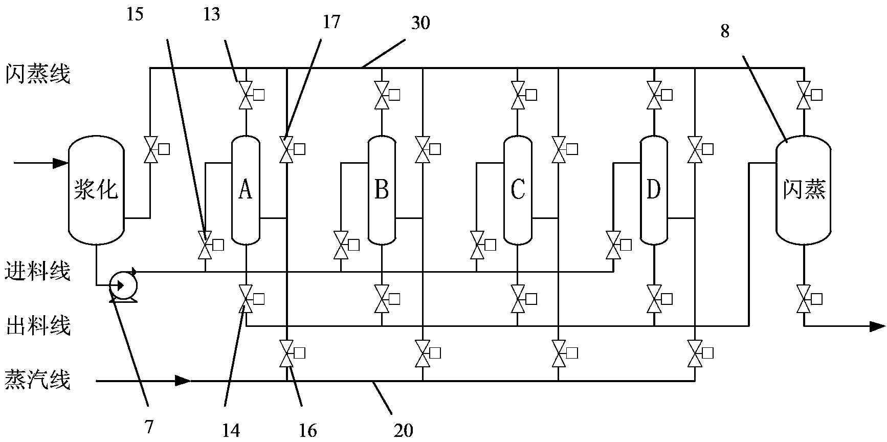
[0061] Such as figure 1 , 2 As shown, the hydrothermal system adopts 1 slurry reactor 6, 4 hydrothermal reactors A, B, C, D and 1 flash reactor 8, has a pipeline 20 for inputting raw steam, and a shared Flash pipeline 30. There are necessary connecting pipes and various valves between each equipment. The following two processing methods can be used:
[0062] The first type: 2-stage flash evaporation: that is, primary flash evaporation: each hydrothermal reactor conducts a steam flash with another hydrothermal reactor; secondary flash evaporation: the material of each hydrothermal reactor Enter the flash reactor for a flash evaporation. The working sequence of each hydrothermal reaction unit is: feed material, input secondary steam, original steam, hydrothermal reaction, output secondary steam (for steam flash heat exchange of another hydrothermal reactor), discharge to flash reactor. In order to enable flash heat exchange between the hydrothermal reactors, the above four...
Embodiment 2
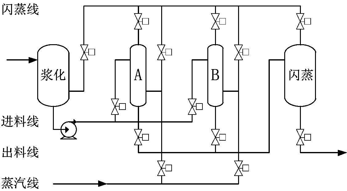
[0065] Such as image 3 As shown, on the basis of the above-mentioned embodiment 1, the hydrothermal system is changed to two hydrothermal reactors A, B, and two stages of flash evaporation. That is to say, both hydrothermal reactor A and hydrothermal reactor B complete the flash evaporation of steam once, and the sludge flowing out from hydrothermal reactor A and B enters the flash reactor to complete the final flash evaporation. In this embodiment, the hydrothermal reaction temperature is 160° C., and the reaction time is 105 minutes. After hydrothermal treatment, the sludge is cooled and dehydrated by a heat exchanger. As a result of the reaction, 27% of the suspended solids (SS) were dissolved, and the supernatant COD (SCOD) was 20,000 mg / L. The solids content of the dewatered cake was 59%. The raw steam consumption of the system is 0.25t / t sludge.
Embodiment 3
[0067] Such as Figure 4 As shown, on the basis of the above-mentioned embodiment 1, the hydrothermal system is changed to three hydrothermal reactors A, B, and C, and two stages of flash evaporation. That is, each of hydrothermal reactors A, B, and C completes one flash of steam respectively, and completes the flash steam heat exchange between hydrothermal reactors A and B, B and C, and A and C; from the hydrothermal reaction After the sludge flowing out of vessels A, B, and C enters the flash reactor, the final flash evaporation is completed. In this embodiment, the hydrothermal reaction temperature is 180° C., and the reaction time is 90 minutes. After hydrothermal treatment, the sludge is cooled and dehydrated by a heat exchanger. As a result of the reaction, 30% of the suspended solids (SS) were dissolved, and the supernatant COD (SCOD) was 20,000 mg / L. The solid content of the dewatered cake was 60%. The raw steam consumption of the system is 0.20t / t sludge.
PUM
 Abstract
Description
Claims
Application Information
 - R&D
- Intellectual Property
- Life Sciences
- Materials
- Tech Scout
- Unparalleled Data Quality
- Higher Quality Content
- 60% Fewer Hallucinations
Browse by: Latest US Patents, China's latest patents, Technical Efficacy Thesaurus, Application Domain, Technology Topic, Popular Technical Reports.
© 2025 PatSnap. All rights reserved.Legal|Privacy policy|Modern Slavery Act Transparency Statement|Sitemap|About US| Contact US: help@patsnap.com