
Vapor chamber and method for manufacturing same

A vapor chamber and heating plate technology, applied in indirect heat exchangers, lighting and heating equipment, electrical components, etc., can solve the problems of affecting the heat dissipation and conduction efficiency of the working medium 7, increasing the production cost, and complicated manufacturing, etc., to achieve the reflow effect Significant, simplified production, less process effect

Active Publication Date: 2013-11-20
东莞维玺温控技术有限公司
View PDF3 Cites 37 Cited by
  • Summary
  • Abstract
  • Description
  • Claims
  • Application Information

AI Technical Summary

Problems solved by technology

This structure needs to sinter the capillary structure layer 22 on both sides of the heating plate 2 and the heat dissipation plate 3, which increases the production cost and wastes materials, because the capillary structure layer 22 in the condensation area 31 on the heat dissipation plate 3 will store a large amount of condensed work. If the medium 7 cannot be guided in time to flow into the evaporation area 21 at the heating plate 2, it will greatly affect the heat dissipation efficiency of the vaporized working medium 7 on the heat dissipation plate 3
[0008] Both of the above two structures have disadvantages such as complex manufacturing and high cost.

Method used


Image

  • Vapor chamber and method for manufacturing same
  • Vapor chamber and method for manufacturing same
  • Vapor chamber and method for manufacturing same

Examples


Embodiment Construction

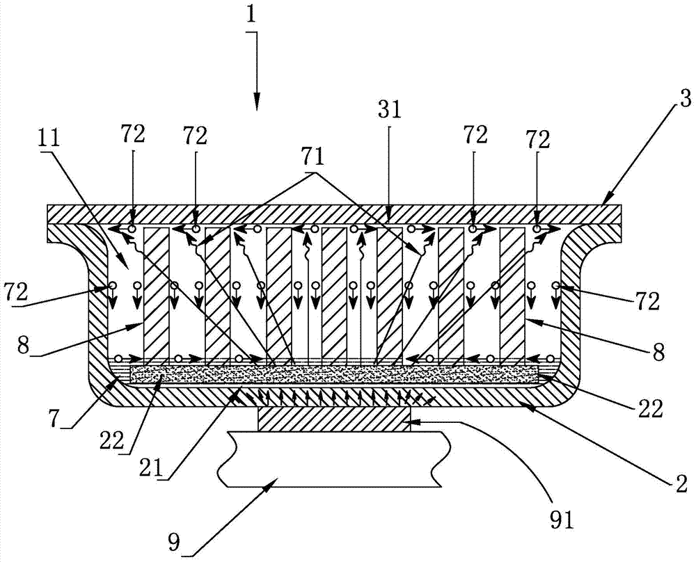
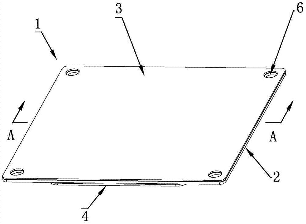
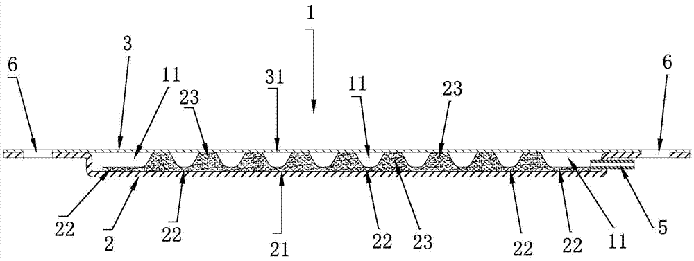
[0043] Such as figure 2 , 3, 4, the vapor chamber 1 of the present invention is composed of a heat-absorbing heat-receiving plate 2 and a heat-dissipating plate 3 that is welded together with the heat-receiving plate 2 and plays a role in heat dissipation. The outer surface of the heat-receiving plate 2 and the heat source of the electronic component 9 91, the outer surface of the heat dissipation plate 3 is in contact with the fins of the peripheral device, and a mounting hole 6 is provided around the vapor chamber 1 . The heat receiving plate 2 and the heat dissipation plate 3 are made of metal materials with good thermal conductivity, such as copper or aluminum. The heat receiving plate 2 and the heat dissipation plate 3 can be made of the same metal, or can be used in combination of different metals. In the present invention, the thin plate made of oxygen-free copper is preferred to make the heating plate 2 and the heat dissipation plate 3, and the thickness of the thin ...


PUM

PropertyMeasurementUnit
Thicknessaaaaaaaaaa
Thicknessaaaaaaaaaa

Abstract

The invention discloses a vapor chamber and a method for manufacturing the same. The vapor chamber is simple in structure, low in cost and good in heat conduction effect and can be manufactured easily and conveniently. The vapor chamber comprises a heated plate and a flat heat dissipation plate. A groove is formed in the inner surface of the heated plate, the flat heat dissipation plate is welded with the heated plate, a vacuum inner cavity is formed between the heat dissipation plate and the groove, working media are filled in the vacuum inner cavity, a part, which is positioned in the vacuum inner cavity, of the heated plate is provided with capillary structure layers, and elemental metal powder is sintered to form each capillary structure layer. The vapor chamber and the method have the advantages that the vapor chamber is simple in manufacture, and the working media on evaporation and condensation zones can be quickly adsorbed by the capillary structure layers, so that high-speed circulation and fast heat conduction effects can be realized; support columns with capillary structures are further arranged in the vacuum inner cavity, accordingly, a condensed vapor backflow effect is obvious, and a sinking or cracking deformation phenomenon of the vapor chamber due to excessively high temperature or external pressure is further prevented; heat can be dissipated evenly by the aid of the vapor chamber, heat resistance of the vapor chamber is reduced, the method for manufacturing the vapor chamber is simple, processes are few, operation is easy, the cost is low, and the vapor chamber and the method are suitable for automatic, intensive and large-scale production.

Description

technical field [0001] The invention relates to a radiator for dissipating working heat of electronic components and a manufacturing method thereof, in particular to a vapor chamber for conducting away working heat of an IC chip and a manufacturing method thereof. Background technique [0002] With the advancement of technology, today's electronic equipment is developing towards multi-function, high speed, and small size. The heat generated by IC chips per unit area has increased significantly. How to improve heat dissipation methods has always been a major challenge for the industry. Taking the CPU of a computer server as an example, its calorific value has exceeded 100W / cm 2 , How to effectively dissipate the working heat generated by the small-area CPU to the environment, the cooling technology must be continuously improved to improve the heat dissipation efficiency. [0003] In the prior art, the mainstream cooling methods are mainly fans, fins, and fins combined with h...

Claims


Application Information

Patent Timeline
IPC IPC(8): F28D15/04H01L23/427H01L23/367B22F7/08
Inventor 施金城
Owner 东莞维玺温控技术有限公司
Learn More