
Coherent optical time-domain reflectometer based on detection frequency coding

A time-domain reflectometer and frequency coding technology, applied in the field of communication, can solve problems such as low Brillouin threshold, reduce the difficulty of modulation and control, facilitate acquisition and processing, and improve the signal-to-noise ratio.

Active Publication Date: 2013-11-20
STATE GRID CORP OF CHINA +5
View PDF4 Cites 22 Cited by
  • Summary
  • Abstract
  • Description
  • Claims
  • Application Information

AI Technical Summary

Problems solved by technology

The frequency of the frequency pulse involved in the method jumps with time but the laser power is continuous. Continuous laser light enters the erbium-doped fiber amplifier in the fiber line to suppress the transient effect and avoid optical surges. However, the frequency pulse is a frequency sweep Yes, in order to stabilize the coherent intermediate frequency signal generated by the probe light and the local oscillator light, the frequency of the local oscillator light should be changed accordingly. In addition, the frequency sweep does not change the continuity and linewidth of the laser. The Brillouin of the continuous light Threshold is very low, which limits the peak power of the frequency pulse and thus limits the dynamic range of the measurement

Method used


Image

  • Coherent optical time-domain reflectometer based on detection frequency coding
  • Coherent optical time-domain reflectometer based on detection frequency coding
  • Coherent optical time-domain reflectometer based on detection frequency coding

Examples


Embodiment Construction

[0027] The specific implementation manners of the present invention will be further described in detail below in conjunction with the accompanying drawings.

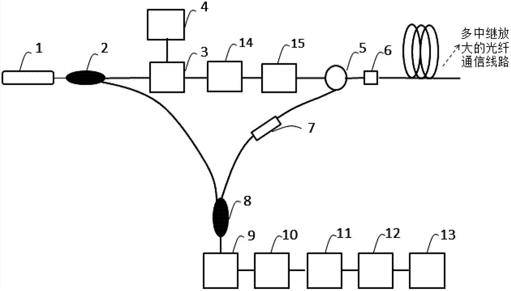
[0028] This embodiment provides a coherent optical time domain reflectometer based on detection frequency coding, which includes:

[0029] Laser 1, configured to provide probe light, fill light and single-frequency local oscillator light;

[0030] The first coupler 2 is used for light splitting;

[0031] The frequency encoder 3 is an electro-optic phase modulator or an electro-optic intensity modulator, which is used to modulate the single-frequency continuous laser and obtain frequency pulse output;

[0032] RF driver 4, select RF generator, such as Agilent's E8257D, the RF range is from 200kHz to 26.5GHz, it provides frequency coded RF signal to drive the phase modulator;

[0033] The circulator 5 provides respective channels for the sending and receiving of light;

[0034] Optical interface 6, used for optical path...


PUM


Abstract

The invention discloses a coherent optical time-domain reflectometer based on detection frequency coding, which comprises a laser, a first coupler, a frequency coder, a radio-frequency driver, a circulator, an optical interface, an optical filter, a second coupler, a photoelectric detector, a radio-frequency amplifier, a data acquisition module, a signal processing module and a display module. Laser light emitted by the laser passes through the frequency coder for frequency coding to obtain pulses of detection frequency pulse light and filling light which is complementary to the time sequence of the detection frequency pulse light. The frequency of the pulse of the detection frequency pulse light is different from the frequency of the pulse of the filling light. After the respective backward Raleigh scattering signals of the detection frequency pulse light and the filling light in an optical fiber line are fed back, the detection frequency pulse light and the filling light enter the optical filter through the third port of the circulator, the filtered detection light signal is coherent with local oscillator light at the second coupler, then coherent medium-frequency signals are output by the photoelectric detector and finally the medium-frequency signals are acquired and processed to obtain a time-domain curve which reflects the characteristics of the optical fiber line.

Description

technical field [0001] The invention belongs to the communication field, and in particular relates to a coherent optical time domain reflectometer used for optical fiber communication line characterization, event identification and fault location. Background technique [0002] Coherent optical time-domain reflectometry is usually used to monitor multi-relay ultra-long-distance optical fiber communication lines such as transoceanic submarine optical cables. Coherent optical time domain reflectometry uses the principle of lidar to locate the scattering and / or reflection point by injecting a detection light pulse into the optical fiber and recording the return time of the Rayleigh scattered light and / or reflected light of the light pulse in the optical fiber. The pulse width of the optical pulse corresponds to the spatial resolution of the measurement, and the two are proportional to each other. For example, the detection optical pulse width of 1 microsecond corresponds to the ...

Claims


Application Information

Patent Timeline
IPC IPC(8): H04B10/071
CPCH04B10/071G01M11/3109
Inventor 吕立冬梁云李炳林郭经红何金陵孙志峰李垠韬
Owner STATE GRID CORP OF CHINA
Learn More