Thin film deposition preparation method and preparation method of nano-fiber structure flexible buffer layer

A thin film deposition and nanofiber technology, applied in the field of materials, can solve the problems of peeling off of protective coatings, large differences in thermal expansion coefficients, equipment damage, etc., and achieve the effects of good flexibility and insulation, small oxygen diffusion coefficient, and good performance.

Inactive Publication Date: 2013-11-27
UNIV OF ELECTRONICS SCI & TECH OF CHINA
View PDF5 Cites 2 Cited by
  • Summary
  • Abstract
  • Description
  • Claims
  • Application Information

AI Technical Summary

Problems solved by technology

Because the physical properties of ceramic and metal blade materials are very different, especially their thermal expansion coefficients are very different. Often the thermal expansion coefficient of metal materials is 2 to 3 times that of ceramic materials. Therefore, when metal blades are subjected to high and low temperature thermal cycles, Due to the difference in thermal expansion coefficient, a large thermal stress is generated. If there is no proper thermal stress release mechanism, the protective coating will inevitably fall off, which will threaten the healthy and safe operation of the blade, an

Method used


Image

  • Thin film deposition preparation method and preparation method of nano-fiber structure flexible buffer layer
  • Thin film deposition preparation method and preparation method of nano-fiber structure flexible buffer layer
  • Thin film deposition preparation method and preparation method of nano-fiber structure flexible buffer layer

Examples


Embodiment 1

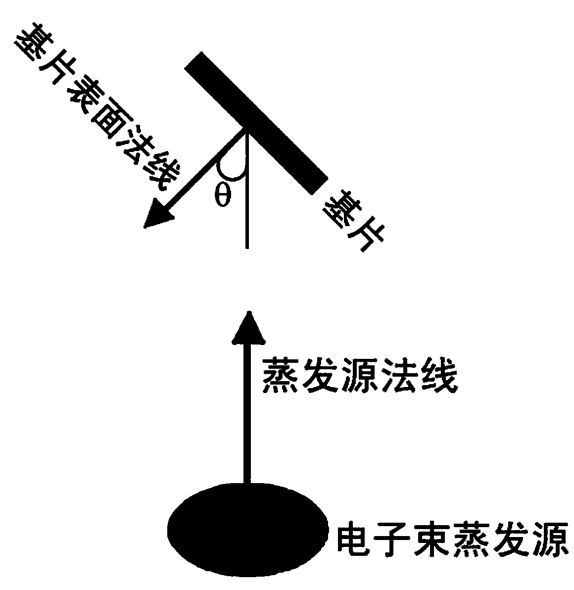
[0019] Example 1 Electron beam evaporation to prepare obliquely arranged nanofibrous structure Al 2 o 3 film

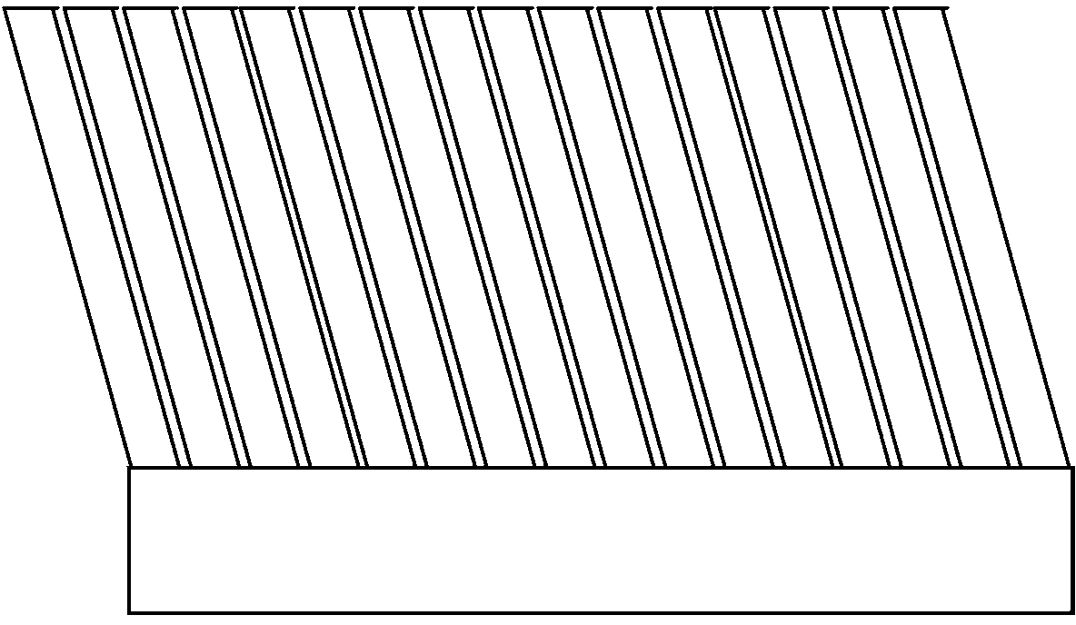
[0020] Al was deposited by electron beam evaporation 2 o 3 film, the normal of the substrate surface and the normal of the evaporation source are at an angle of 45°, and the temperature of the substrate is 200°C, the prepared Al 2 o 3 The thickness of the film is 3 microns, and its cross-sectional appearance is as attached Figure 4 As shown, it presents a typical structure characteristic of obliquely arranged nanofibers.

Embodiment 2

[0021] Example 2 Electron beam evaporation to prepare obliquely aligned nanofibrous structure Al 2 o 3 flexible cushioning layer

[0022] First use the process conditions as in Example 1 to prepare a tilted nanofiber structure Al with a thickness of about 2.5 microns. 2 o 3 thin film, then adjust the normal of the substrate surface and the normal of the evaporation source to an angle of 0°, and continue to deposit about 7.5 microns thick Al 2 o 3 thin film so that the entire Al 2 o 3 The film thickness reaches about 10 microns. Prepared Al 2 o 3 The cross-sectional morphology of the film is as attached Figure 5 Shown, visible: the entire Al 2 o 3 The film can be divided into two parts, the first part is about 2.5 microns thick with nanofibrous structure Al 2 o 3 film, which acts as a flexible buffer layer throughout the film to relieve film thermal stress during thermal shock; the second part is about 7.5 microns thick Al 2 o 3 Continuous film, the film structu...


PUM

PropertyMeasurementUnit
Thicknessaaaaaaaaaa
Thicknessaaaaaaaaaa

Abstract

The invention provides a thin film deposition preparation method and a preparation method of a nano-fiber structure flexible buffer layer, and belongs to the technical field of materials. The thin film deposition preparation method comprises a temperature rise step and a deposition step. The thin film deposition preparation method is characterized in that in the deposition step, an included angle between the normal line of a deposition source and the normal line of the surface of a substrate ranges from 30 to 80 degrees. The preparation method provided by the invention has the advantages that a heat stress release mechanism with excellent performance is provided, and a nano-fiber structure Al2O3 flexible buffer layer thin film prepared by the preparation method has excellent flexibility and insulation property and low oxygen diffusion coefficient.

Description

technical field [0001] The invention belongs to the technical field of materials, in particular to a method for controlling the physical properties of thin film materials. Background technique [0002] With the increasing shortage of fossil fuels and the increasing urgency of environmental protection, on the one hand, the exploration of new alternative energy sources is becoming more and more important, but on the other hand, how to improve the efficiency of traditional energy use to achieve the purpose of energy saving and emission reduction is also very important. The key, for this reason, increasing the combustion temperature of various energy devices has become the most realistic energy-saving and emission-reduction technical solution at present, such as: ultra-supercritical natural coal power generation technology, F-class gas turbine technology, etc. are typical representatives of it. With the continuous increase of combustion temperature, higher and higher requirement...

Claims


Application Information

Patent Timeline
IPC IPC(8): C23C14/34C23C14/30C23C14/08F01D5/28
Inventor 刘兴钊张万里蒋洪川蒋书文李言荣
Owner UNIV OF ELECTRONICS SCI & TECH OF CHINA
Why Eureka
Try Eureka