Laser detection method of residual ammonia gas in solid ammonia storage system

A technology for residual ammonia and ammonia storage, applied in exhaust gas treatment, electrical components, exhaust devices, etc., can solve the problems of reduced adsorption capacity, affecting the use effect, low adsorption and desorption efficiency, etc., and achieves benefits for emission reduction, Reliability and accuracy improvement, high practical value effect

Active Publication Date: 2017-03-15
CHINA FIRST AUTOMOBILE
View PDF5 Cites 0 Cited by
  • Summary
  • Abstract
  • Description
  • Claims
  • Application Information

AI Technical Summary

Problems solved by technology

[0011] CaCl 2 Adsorbed NH 3 After that, it is closely connected with the surrounding particles to form agglomerates with almost no pores, and the rest of the NH 3 Difficult access to the area, resulting in NH 3 The adsorption capacity is greatly reduced, which hinders the formation of ammonium calcium chloride complex; compared with the loose adsorbent powder, the adsorbent solid block formed by direct mechanical compression has fewer ammonia gas transmission channels, and the adsorption and desorption low efficiency; in addition, CaCl 2 Adsorbed NH 3 After the volume expands, the solid block is easy to pulverize and break, which affects the use effect

Method used


Image

  • Laser detection method of residual ammonia gas in solid ammonia storage system
  • Laser detection method of residual ammonia gas in solid ammonia storage system
  • Laser detection method of residual ammonia gas in solid ammonia storage system

Examples


Embodiment 1

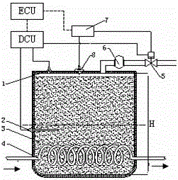
[0039] Prepare a stainless steel storage tank with an effective volume of 32L, with a height of H=460mm and a diameter of 300mm. Fill the tank with 15kg of solid ammonia storage material to complete the ammonia filling; use commercially available pressure sensor 1, temperature sensor 2, and ammonia gas metering Valve 5, filter 6 and laser displacement sensor 8, according to as figure 1 , 2 , The structure shown in 3 and 4 is installed on the storage tank, and the connection between the control display and the laser displacement sensor 8 and the ECU is completed, and the connection between the ECU and the DCU and the ammonia metering valve 5 and the storage tank is completed; the antifreeze conduit, ammonia Connect the air inlet and outlet, and complete the ammonia filling; then match the system with the aging test bench of the 8.6L engine, in which the antifreeze pipe 4 is connected to the engine cooling circuit to provide a heat source; at the rated engine speed of 2100rpm, ...

Embodiment 2

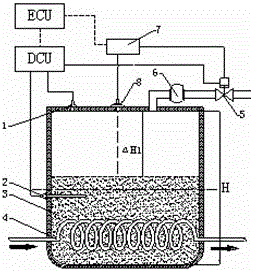
[0041] Adopt the engine prepared by embodiment 1 and the ammonia storage system, at the rated engine speed of 2100rpm, the torque is 1200 Nm to continue the reliability test operation, start the ammonia release valve, after the test is carried out for 133h, the ammonia pressure that the system builds up is still 310kpa, at this time, read the distance from the probe of the laser displacement sensor to the interface of the active material, △H2=210mm, which is greater than the rated 45%H of 207mm, and the display controller is a yellow light;

Embodiment 3

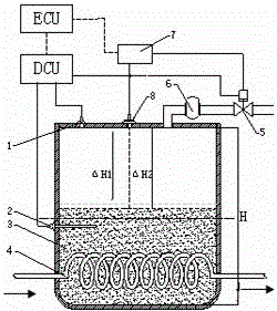
[0043] Adopt the engine and the ammonia storage system after the operation of Example 2, at the rated engine speed of 2100rpm, the torque is 1200 Nm to continue the reliability test operation, start the ammonia release valve, and after the test has been carried out for 3 hours, the ammonia pressure established by the system is still It is 229kpa. At this time, read the distance from the probe of the laser displacement sensor to the interface of the active material, △H3=218mm, which is greater than the rated 47%H of 216mm, and the display controller is a red light.


PUM


Abstract

The invention relates to a laser measurement method for the ammonia residue of a solid ammonia storage system, which comprises a pressure sensor, a temperature sensor, a solid ammonia storage material, a storage tank, an anti-icing fluid guide pipe, an ammonia metering valve, a filter, a control display, a laser displacement sensor, a laser emitter and a laser receiver, wherein the anti-icing guide pipe is placed in the solid ammonia storage material at the bottom of the ammonia storage tank; the pressure sensor and an ammonia outlet pipe are arranged at the top of the ammonia storage tank; the temperature sensor is arranged on the tank body of the ammonia storage tank; the filter and the ammonia metering valve are arranged on the ammonia outlet pipe. The laser measurement method comprises the steps as follows: a laser distance measurement system is placed in the solid ammonia storage system in advance; when the amount of the ammonia in the system is changed, the stacking volume of active material is accordingly and correspondingly changed, a distance between a measurement point and the interface of the active material is accurately measured in a laser distance measurement method, a measurement signal is fed back to a control unit, and the ammonia residue is measured. The laser measurement method has the characteristics of smart conception, simple process, easiness for control and maintenance, low cost, high accuracy and reliability, and the like.

Description

technical field [0001] The invention relates to a laser detection method for residual ammonia gas in a solid ammonia storage system, which is applied to an SCR post-treatment system of automobile tail gas and an FCEV fuel cell system. Background technique [0002] At present, the world is facing comprehensive challenges of energy and environment. People are still facing many problems in the selection of technical means to meet the emission standards of traditional vehicles, and in the fuel supply technology of new energy vehicles. [0003] The SCR post-treatment system relies on the accurate supply of urea reducing agent and decomposes it into ammonia gas at the front end of the catalyst to remove NOX hazards, so as to purify the exhaust gas and achieve the vehicle's National 4 or above standards. However, in actual use Among them, there are many deficiencies and difficulties in the metered injection of liquid urea that relies on urea decomposed into ammonia gas. For exampl...

Claims


Application Information

Patent Timeline
Patent Type & Authority Patents(China)
IPC IPC(8): F01N3/20F01N11/00H01M8/04313
CPCY02E60/50Y02P70/50Y02T10/40
Inventor 张克金崔龙陈慧明
Owner CHINA FIRST AUTOMOBILE
Why Eureka
Try Eureka