
Dynamic testing device and method for ablation rate of material

A dynamic testing and testing device technology, applied in material excitation analysis, electrical excitation analysis, etc., can solve the problem that the anti-interference ability of the laser receiver, the stability of the bench and the feeding accuracy are quite high and cannot be well characterized. The problem of measuring the ablation material line, lack of dynamic ablation experiments, etc., achieves the effect of easy control of the test temperature, good safety, and low test cost

Active Publication Date: 2013-11-27
HARBIN INST OF TECH
View PDF5 Cites 24 Cited by
  • Summary
  • Abstract
  • Description
  • Claims
  • Application Information

AI Technical Summary

Problems solved by technology

This method is affected by the spot size of the laser transmitter. The ablation rate of the ablation material line to be tested is actually the cumulative value of multi-segment average data rather than real-time data. It cannot characterize the ablation material line to be tested well. The change of the ablation amount with the ablation time, at the same time, the anti-interference ability of the laser receiver, the stability of the gantry and the feeding accuracy are quite high, and there are certain technical limitations.
[0006] At present, there is a lack of research on dynamic ablation experiments in China, and a breakthrough in dynamic ablation experiments is urgently needed

Method used


Image

  • Dynamic testing device and method for ablation rate of material
  • Dynamic testing device and method for ablation rate of material
  • Dynamic testing device and method for ablation rate of material

Examples


Embodiment 1

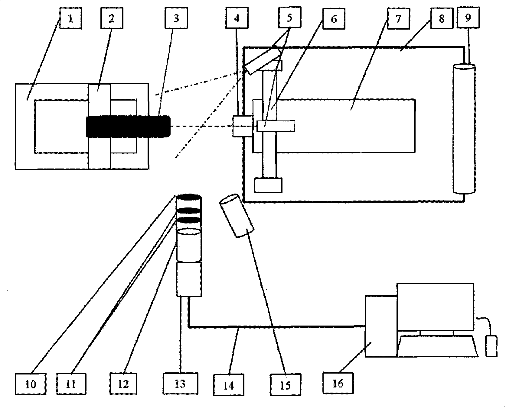
[0025] This embodiment is a dynamic test device for ablation rate of materials, mainly comprising: a horizontal moving platform 1; a vise 2 is fixed on the horizontal moving platform 1 with bolts; the ablation material 3 to be tested is clamped by the vise 2; A positioning bracket 6 is installed at a certain distance from the horizontal mobile platform 1; the U-shaped clamp on the positioning bracket 6 clamps the arc heating spray gun 7; The two inline lasers 5 can form a positioning cross-structure laser on the axial end face of the ablation material 3 to be measured; the nozzle of the arc heating spray gun 7 is threaded to connect the water cooling jacket 4; the water cooling jacket 4 passes through the water pipe 8 and the circulation The water tank 9 is connected; the nozzle of the arc heating spray gun 7 faces the ablation material 3 to be tested at a certain distance; a CCD camera 13 is installed on one side of the ablation material to be measured and the axis of the arc ...

Embodiment 2

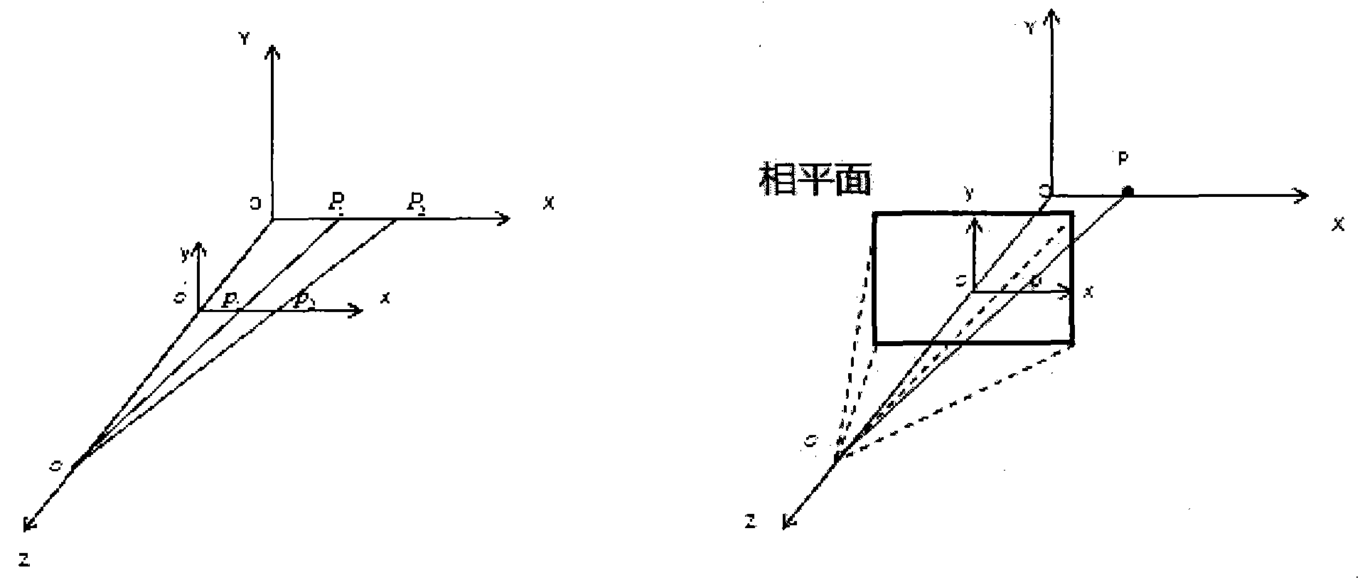
[0030] The principle of image processing:

[0031] The central axis of the ablation material to be tested is the same as the direction of flame injection, which is set as the X axis, the vertical direction is established as the Y axis, and the direction perpendicular to the XOY plane is set as the Z axis, as figure 1 As shown; the camera is placed on the Z axis so that the phase plane of the camera is parallel to the X axis, which is convenient for image processing; the filter group is installed in front of the lens of the CCD camera with various focal lengths; a 405nm filter is installed on the Z axis and the Y axis direction For the Ziguang inline laser emitter, the laser projection planes are respectively located in the XOZ and XOY planes, so that the two laser beams form a positioning cross-structure laser on the end surface of the ablation material to be tested; the two laser emitters actually emit two A fan-shaped area, the intersection line of which is located on the X-...


PUM

PropertyMeasurementUnit
wavelengthaaaaaaaaaa

Abstract

The invention relates to a dynamic testing device and method for the ablation rate of a material. The dynamic testing device comprises a CCD (Charge Coupled Device) camera, wherein a light filter group is mounted in front of a multi-focal-length camera lens and is used for blocking highlight emitted from a test piece and simultaneously allowing the transmission of lasers for demarcating a position; the position is demarcated by the positioning cross-shaped lasers; an electric arc heating spray gun is utilized to heat the end face of a to-be-tested ablative material; the whole device is positioned by a positioning bracket to enable the electric arc heating spray gun and the to-be-tested ablative material to be located on the same axis, and the point of intersection of the positioning cross-shaped lasers is throughout maintained on the center of the end face during a backward movement process of the end face; the CCD camera and the to-be-tested ablative material are located in the same horizontal position, a phase plane of the CCD camera is parallel with the axis of the to-be-tested ablative material, and the CCD camera is connected with a computer and is used for collecting and storing test images. According to the dynamic testing device, the dynamic ablation quantity test experiment of materials, such as graphite and vycor, can be implemented under an electric arc heating condition; the dynamic testing device has the advantages that the experiment cost is low, and that the experiment temperature is easy to control.

Description

technical field [0001] The invention relates to a dynamic testing device and method for material ablation rate. Background technique [0002] In the development of heat protection technology, the most mature heat protection mechanism is ablative heat protection. Ablative heat shielding materials are commonly used on RV exterior surfaces. During the process of the reentry vehicle returning to the atmosphere, under the action of heat flow, the ablation heat shield of the reentry vehicle undergoes various physical and chemical changes that absorb heat energy, such as decomposition, melting, evaporation, and sublimation, and is taken away by the mass consumption of the material itself. A large amount of heat energy is used to prevent the heat from being introduced into the interior of the aircraft. [0003] The ablation of materials directly affects the aerodynamic shape of the aircraft. Accurate testing of ablation rate is the basis and premise of thermal structure design. At...

Claims


Application Information

Patent Timeline
Patent Type & Authority Applications(China)
IPC IPC(8): G01N21/67
Inventor 孟松鹤金华骄利闯易法军许承海解维华
Owner HARBIN INST OF TECH
Learn More