Laser amplifier

A technology of laser amplifiers and laser crystals, which is applied to lasers, laser components, phonon exciters, etc., can solve the problem of low output power, low overlapping efficiency of seed light and pump gain regions, and low extraction efficiency of laser amplifiers etc. to achieve the effects of low cost, improved efficiency and energy utilization, and simple structure

Inactive Publication Date: 2013-11-27
CHANGSHA UNIVERSITY OF SCIENCE AND TECHNOLOGY
View PDF5 Cites 7 Cited by
  • Summary
  • Abstract
  • Description
  • Claims
  • Application Information

AI Technical Summary

Problems solved by technology

However, due to the inefficient overlap between the seed light and the pump gain region in this...

Method used


Image

  • Laser amplifier
  • Laser amplifier
  • Laser amplifier

Examples


Embodiment 1

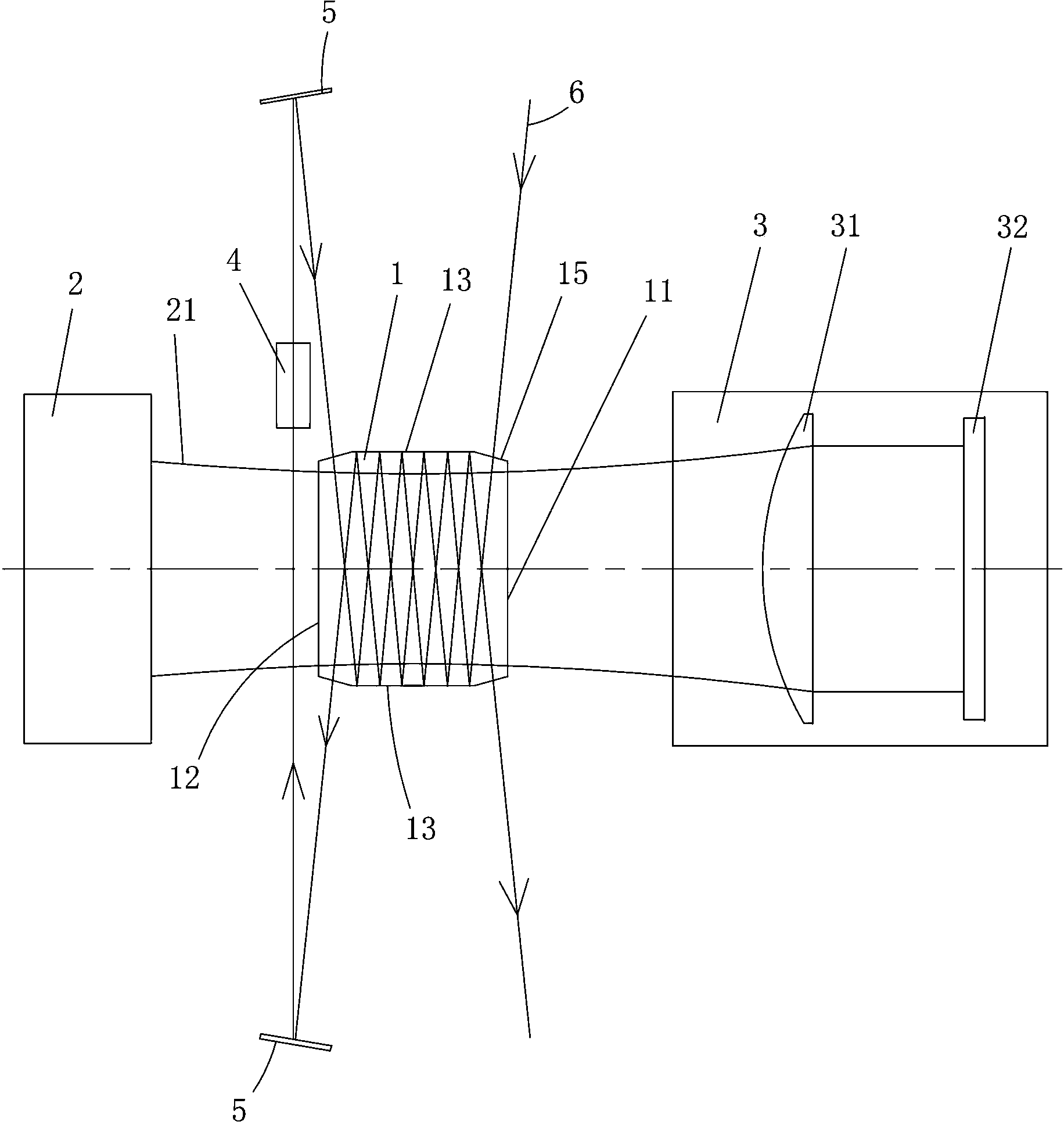
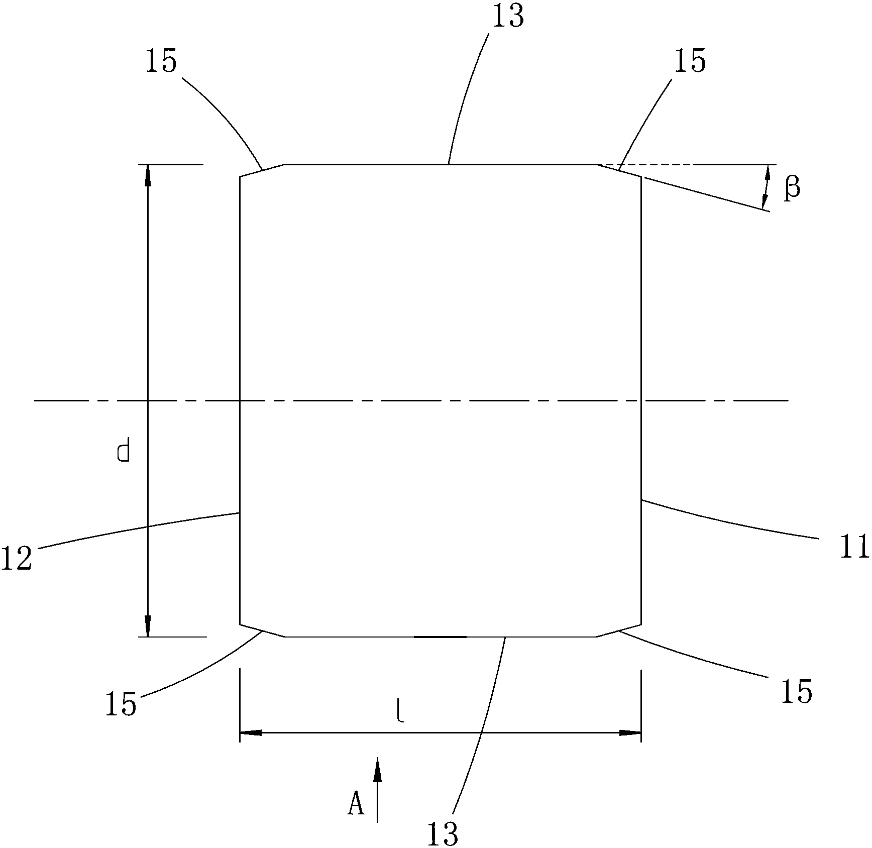
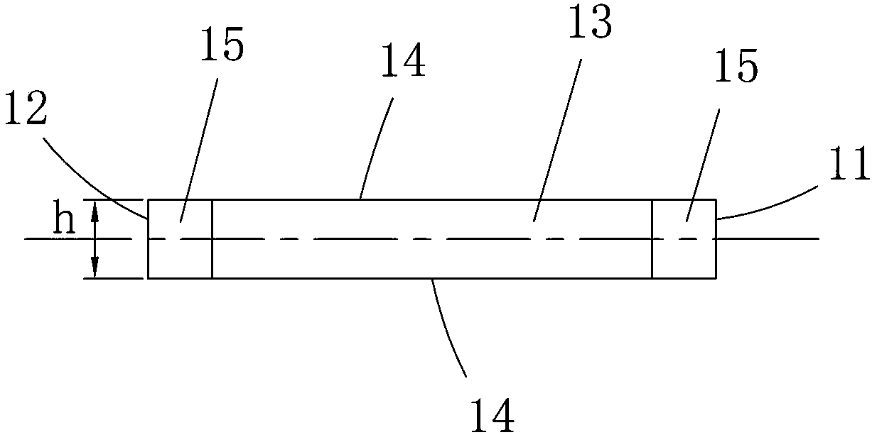
[0031] Such as figure 1 As shown, the laser amplifier of the present invention includes a pumping system 2 and a slab laser crystal 1, the pumping system 2 is used to pump the slab laser crystal 1, and the slab laser crystal 1 absorbs the pump light 21 to cause the number of particles Inversion, the energy stored in the slab laser crystal 1 forms a gain region. The two ends in the length direction of the slab laser crystal 1 are respectively the first end 11 and the second end 12, the two sides in the width direction of the slab laser crystal 1 are total reflection surfaces 13, and the two sides in the thickness direction of the slab laser crystal 1 are for the heat sink surface 14 (see image 3 ). The heat dissipation surface 14 adopts a commonly used copper water cooling device, and the heat dissipation surface 14 and the copper are in close contact with each other through indium. One side of the end face of the second end 12 is provided with a mirror assembly. During ope...

Embodiment 2

[0042] Such as Figure 6 As shown, the structure of this embodiment is roughly the same as that of Embodiment 1, except that the size of the slab laser crystal 1 is l=11.5 mm in length, d=12 mm in width, and h=2 mm in thickness. Because the length of slab laser crystal 1 is different from embodiment 1, the number of reflections of seed light 6 in slab laser crystal 1 is also different from embodiment 1 (the reflection principle of seed light is the same as embodiment 1, and here No longer).

Embodiment 3

[0044] Such as Figure 7 , Figure 8 As shown, the difference between the structure of this embodiment and embodiment 1 is that the material of slab laser crystal 1 is Nd:YVO 4 , the size of the slab laser crystal 1 is l=12.5mm in length, d=10.2mm in width, h=2mm in thickness, and the doping concentration is 1%. The crystal is α Direction cut, length 12.5mm for c axis direction. The pumping system 2 and the pumping light reflection matching system 3 are respectively arranged on both sides of the width direction of the slab laser crystal.

[0045] In this embodiment, the included angle β is 7 degrees, and the projected length of the cut surface 15 on the corresponding total reflection surface 13 is 1.25 mm. The total reflection surface 13 is coated with a pump light high-transmission film and a seed light high-reflection film, and the cut surface 15 is coated with a seed light high-transmission film.

[0046] The pump light with a central wavelength of 888nm enters the sla...


PUM

PropertyMeasurementUnit
Lengthaaaaaaaaaa
Widthaaaaaaaaaa
Thicknessaaaaaaaaaa

Abstract

The invention discloses a laser amplifier which comprises a slab laser crystal (1). The two ends of the slab laser crystal (1) in the length direction are the first end (11) and the second end (12) respectively. The two side faces of the slab laser crystal (1) in the width direction are fully-reflecting surfaces (13). Seed light (6) is slantly emitted in from the first end (11) and emitted out from the second end (12) relative to the fully-reflecting surfaces (13). A reflector component (6) used for slantly reflecting the seed light (6) emitted out from the second end (12) back to the second end (12) relative to the fully-reflecting surfaces (13) and enabling the seed light (6) to be emitted out from the first end (11) is arranged on one side of the end face of the second end (12). The laser amplifier is simple in structure, low in cost, high in overlapping efficiency and extracting efficiency and capable of obtaining high-power high-beam-quality laser output.

Description

technical field [0001] The invention mainly relates to the field of laser amplifiers, in particular to a slab laser amplifier. Background technique [0002] In order to obtain high-power laser output, a laser amplifier is usually used to amplify the laser signal. Traditional laser amplifiers will produce severe thermal lens effect and thermo-optic distortion effect under thermal load conditions, which will reduce the beam quality and limit the output power. The slab laser crystals widely used at present can effectively reduce the thermal lens effect and Due to the influence of thermo-optic distortion effect, high-power laser output can be obtained while taking into account the beam quality. Therefore, slab laser amplification technology is an important technology to obtain high power and high beam quality laser. At present, this kind of laser amplification technology generally cuts the two ends of the slab laser crystal into a 45° angle or a Brinell angle slope, so that t...

Claims


Application Information

Patent Timeline
IPC IPC(8): H01S3/081H01S3/06H01S3/16
Inventor 彭润伍杨满蓉
Owner CHANGSHA UNIVERSITY OF SCIENCE AND TECHNOLOGY
Why Eureka
Try Eureka