Microfluidic system and method for detecting and screening single beam biological cells

A microfluidic system and biological cell technology, which is applied in the field of microfluidic system for single-beam biological cell detection and screening, can solve problems that restrict the development of cancer cell detection and control systems, eliminate the interference of background fluorescence, and reduce cytotoxicity , cost reduction effect

Active Publication Date: 2013-12-11
SOUTH CHINA NORMAL UNIVERSITY
View PDF1 Cites 21 Cited by
  • Summary
  • Abstract
  • Description
  • Claims
  • Application Information

AI Technical Summary

Problems solved by technology

These two shortcomings restrict the development of ca...

Method used


Image

  • Microfluidic system and method for detecting and screening single beam biological cells
  • Microfluidic system and method for detecting and screening single beam biological cells
  • Microfluidic system and method for detecting and screening single beam biological cells

Examples


Embodiment 1

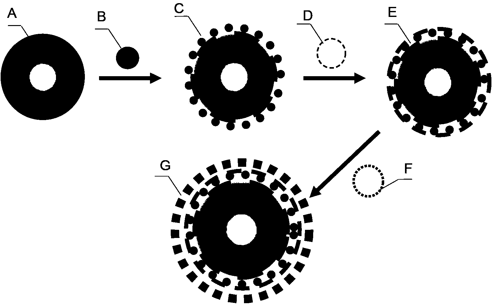
[0032] In this example, the problematic cells are cervical cancer HeLa cells. Before screening, it is necessary to prepare upconversion luminescent nanoprobes. The conversion process is as follows: figure 1 As shown, A is the core structure of upconversion nanoparticles coated with oleic acid; B is 5-mercaptosuccinic acid (MSA); C is the upconversion nanoparticles wrapped with 5-mercaptosuccinic acid (MSA); D is Polyallylamine hydrochloride (PAH); E is PAH-MSA-UCNPs; F is CAE8 antibody; G is the upconversion luminescent nanoprobe that completed antibody modification. First, upconversion nanocore-shell particle structures with a size of less than 10 nm were synthesized. Specifically, yttrium trichloride (YCl 3 ), ytterbium trichloride (YbCl 3 ), and erbium trichloride (ErCl 3 ) powder, oleic acid (OA), oleylamine (OM), and 1-octadecene (ODE) were stirred and heated to 110°C under vacuum for 1 hour. Then add sodium oleate (NaOL) powder and anhydrous NH 4 F and pass N at 310...

Embodiment 2

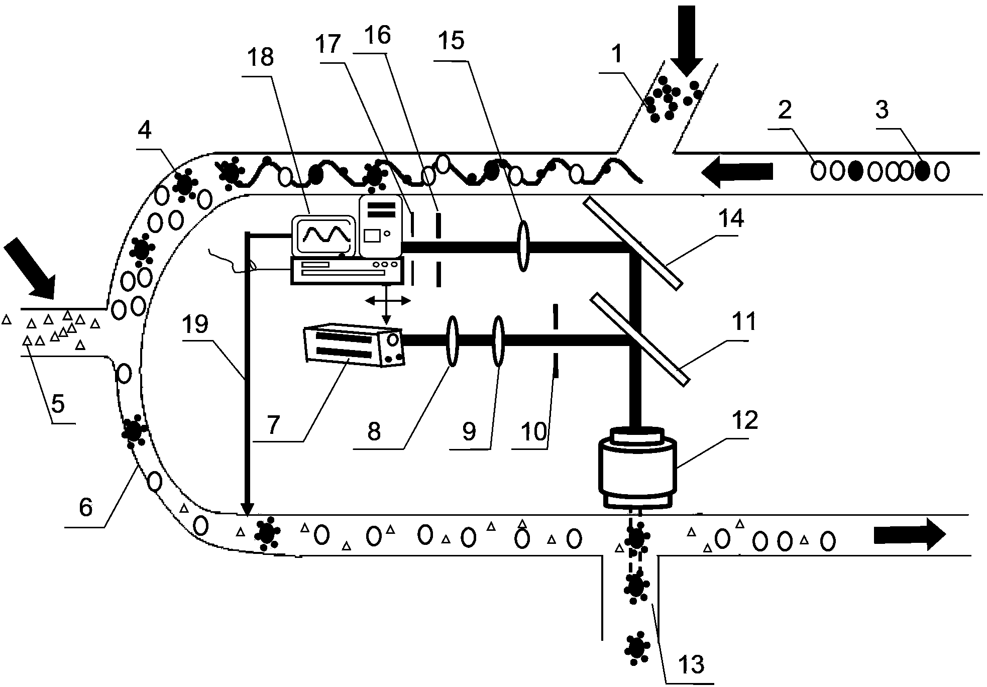
[0040] Present embodiment except following feature other structures are with embodiment 1: as Figure 4 As shown, the optical tweezers device in this embodiment includes a semiconductor laser 7, a beam expander lens 8, a beam shaping lens 9 and a dichromatic mirror 20, wherein the dichromatic mirror 20 is characterized by near-infrared reflection and visible light transmission, and the semiconductor laser 7 The steady-state laser beam that produces passes through beam expander lens 8, beam shaping lens 9 and dichroic mirror 20 successively, and dichroic mirror 20 is placed at an angle of 45 degrees with this laser beam, and is perpendicular to this laser beam and passes through dichroic mirror 20 light In the direction of the axis, the objective lens 12 is coaxially placed below the dichromatic mirror 20, and the dichromatic mirror 20 deflects the laser beam by 90 degrees, and converges on the focal point of the objective lens through the objective lens 12; the detection device...


PUM

PropertyMeasurementUnit
Wavelengthaaaaaaaaaa

Abstract

The invention discloses a microfluidic system and method for detecting and screening single beam biological cells. The system comprises a detection device, an optical tweezers device, a microfluidic chip, an electric objective table and an objective lens. The method comprises the steps of labeling cells to be detected by using an up-conversion luminescence nanometer material to obtain problem cells with up-conversion luminescence nanometer probe labels and normal cells without labels; carrying out laser scanning on all cells, wherein the problem cells with the up-conversion luminescence nanometer probe labels emit up-conversion light on the condition of being induced by near-infrared band laser, and once a detector detects an up-conversion fluorescence signal, the cells are screened out by using an optical tweezers technology; and finally, detecting, counting and separating the problem cells. The system and method are reduced in cost and increased in signal to noise ratio of the signals to be detected, has the great technical development application space and wide market prospect, and is suitable for structure microminiaturized devices for cancer cell diagnosis and control structures based on microfluidic chips.

Description

technical field [0001] The invention belongs to the interdisciplinary technical fields of nanophotonics, biophotonics and biomedical detection, and specifically relates to a microfluidic system and method for single-beam biological cell detection and screening. Background technique [0002] Nano-biophotonics is an emerging cross-field discipline in recent years. It applies the advantages of non-destructive, fast and real-time detection in optical methods to the fields of life science and medicine. its natural superiority. In the field of cancer cell detection, screening, and research, traditional Raman systems often use two different laser beams, one laser is used to excite fluorescence to detect cancer cells, and the other laser is used as optical tweezers to screen cancer cells after detection . On the one hand, these methods use the Raman method to detect weak signals and a large degree of background fluorescence interference; on the other hand, the dual optical path sy...

Claims


Application Information

Patent Timeline
IPC IPC(8): G01N15/14G01N21/64B01L3/00
Inventor 詹求强刘静赵宇翔
Owner SOUTH CHINA NORMAL UNIVERSITY
Why Eureka
Try Eureka