Cascade utilization method and device of waste gas of flue gas of boiler for thermal power unit

A technology for boiler flue gas and thermal power units, which is applied in preheating, feed water heaters, lighting and heating equipment, etc. It can solve problems such as failure to achieve temperature matching, cascade utilization, small power generation contribution of units, and increased heat transfer area. , to achieve good coal type and seasonal adaptability, load reduction, and good heat transfer effect

Active Publication Date: 2013-12-18
山东英电环保科技有限公司
View PDF8 Cites 5 Cited by
  • Summary
  • Abstract
  • Description
  • Claims
  • Application Information

AI Technical Summary

Problems solved by technology

However, there is a limit to reducing the exhaust gas temperature. On the one hand, when the exhaust gas temperature is relatively low, as the temperature of the flue gas further decreases, the temperature difference with the air decreases, that is, the heat transfer area of ​​the air preheater increases a lot, and the temperature of the flue gas decreases. On the other hand, when the exhaust gas temperature is low and the wall temperature of the preheater tube is lower than the dew point of the flue gas, low-temperature corrosion will occur, and the preheater will need to be replaced after one or two years of operation, and in severe cases, it will need to be replaced within half a year
Another way is to add a low-pressure economizer at the tail of the flue, appropriately increase the heating surface of the economizer, impose waste heat utilization of the flue gas, and increase the temperature of the feed water. The coal burner utilizes the waste heat of the flue gas, which contributes little to the power generation of the unit, and the utilization of heat energy fails to achieve temperature matching and cascade utilization, resulting in a great loss of useful energy

Method used


Image

  • Cascade utilization method and device of waste gas of flue gas of boiler for thermal power unit

Examples


Embodiment Construction

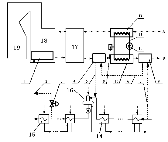
[0029] Accompanying drawing is a kind of specific embodiment of the present invention.

[0030]In the thermal power unit boiler flue gas waste heat cascade utilization device of the present invention, a first low-heating heat exchanger 4 is provided between the air preheater 17 and the flue gas-oil heat exchanger 10, and a first low-heating heat exchanger 4 is installed between the flue gas-oil heat exchanger 10. A second low-pressure heat exchanger 8 is installed on the flue gas outlet side; a water diversion pipe 7 is added to the low-pressure water supply pipe before the first low-pressure heater 14 after the condenser, and a water inlet pipe 5 and a water diversion pipe are added to the water inlet side of the deaerator 16 7 is connected to the water inlet of the second low heating exchanger 8, the water inlet pipe 5 is connected to the water outlet of the first low heating exchanger 4, and the water inlet of the first low heating exchanger 4 is connected to the outlet of t...


PUM


Abstract

The invention discloses a cascade utilization method and device of waste gas of flue gas of a boiler for a thermal power unit. A first low pressure heater heat exchanger is arranged between an air preheater and a flue gas-oil heat exchanger, and a second low pressure heater heat exchanger is arranged at the flue gas outlet side of the flue gas-oil heat exchanger; a diversion pipe is additionally arranged on a low pressure water supply manifold which is arranged at the back of a condenser and in front of a first-stage low pressure heater, and a water inlet pipe is additionally arranged at the water inlet side of a deaerator; the diversion pipe is connected with a water inlet of the second low pressure heater heat exchanger, and the water inlet pipe is connected with a water outlet of the first low pressure heater heat exchanger; and a low pressure water supply pipeline is arranged between the water inlet of the first low pressure heater heat exchanger and the water outlet of the second low pressure heater heat exchanger. Through the arrangement of an additional economizer heating surface, the low pressure heat exchanger, the flue gas-oil heat exchanger and an air-oil heat exchanger, the temperature counterpart and cascade utilization of flue gas waste heat are realized, the boiler efficiency and the unit power generation efficiency are improved, the energy consumption of the thermal power unit is reduced, and meanwhile the carbon dioxide emission is reduced.

Description

technical field [0001] The invention relates to a method and device for cascaded utilization of boiler flue gas waste heat of a thermal power unit, in particular to reducing the exhaust gas temperature of a thermal power unit, improving the thermal efficiency of the boiler and the power generation efficiency of the unit, reducing coal consumption for power generation, and reducing pollution emissions. Background technique [0002] With the development of the economy, the society's demand for electricity is increasing. For China, more than 70% of power plants are coal-fired power plants. Coal-fired power plants have the disadvantages of low efficiency and high pollutant emissions. The energy utilization rate of coal-fired power plants is low, and most of the waste heat energy is discharged into the environment without being utilized. This part of waste heat mainly includes the exhaust steam energy of the steam turbine and the flue gas energy discharged by the boiler. [00...

Claims


Application Information

Patent Timeline
Patent Type & Authority Applications(China)
IPC IPC(8): F22D1/36
Inventor 向文国王伟田鹏李硕
Owner 山东英电环保科技有限公司
Why Eureka
Try Eureka