Optical Automatic Gain Control Circuit

An automatic gain control and circuit technology, applied in the direction of gain control, amplification control, electrical components, etc., can solve the problems of small control range, small dynamic range, and low precision, and achieve wide dynamic range, excellent performance, and high control accuracy Effect

Active Publication Date: 2016-09-28
陕西迈克高新科技实业集团有限公司
View PDF4 Cites 0 Cited by
  • Summary
  • Abstract
  • Description
  • Claims
  • Application Information

AI Technical Summary

Problems solved by technology

[0002] In the optical receiver of cable TV transmission equipment, most of the usual automatic gain control circuits are realized by controlling the attenuation of PIN diodes. This kind of circuit is low in cost, but due to the nonlinearity of PIN diodes, the control range is small and the accuracy is low. ; The other is realized by single-chip microcomputer and numerical control attenuator. The controllability of this scheme is better than that of PIN diode, but when the received power changes, when the MCU in the control circuit sends an adjustment command to the numerical control The internal adjustment of the attenuator is step-by-step, and the electronic pulse will interfere with the transmission signal, and bright spots or bright lines will appear on the screen of the user terminal, and the dynamic range is small

Method used


Image

  • Optical Automatic Gain Control Circuit
  • Optical Automatic Gain Control Circuit

Examples


Embodiment Construction

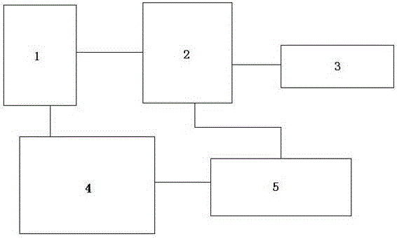
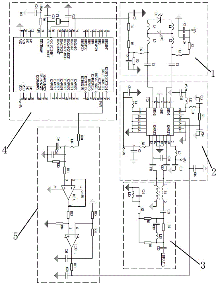
[0020] Optical automatic gain control circuit, including photoelectric conversion and received power detection unit 1, MCU control unit 4, gain-adjustable radio frequency broadband amplifier unit 2, radio frequency broadband network matching unit 3 and operational amplifier unit 5, photoelectric conversion and received power detection unit 1 Respectively connected to the gain-adjustable frequency broadband amplifier unit 2 and the MCU control unit 4, the operational amplifier unit 5 is respectively connected to the MCU control unit 4 and the gain-adjustable RF broadband amplifier unit 2, and the RF broadband network matching unit 3 is connected to the gain-adjustable RF broadband amplifier Unit 2 is connected.

[0021] The photoelectric conversion and received power detection unit 1: it has a photodiode GD1 and a matching circuit, the matching circuit is composed of an inductor L1, an inductor L2, an inductor L4, an inductor L5, and a capacitor C3; the photodiode GD1 converts t...


PUM


Abstract

The present invention relates to an optical automatic gain control circuit. Most of the usual automatic gain control circuits are realized by controlling the attenuation of the PIN diode. This kind of circuit is low in cost, but due to the nonlinearity of the PIN diode, the control range is small and the accuracy is low; when the received power changes, the control When the MCU in the circuit sends an adjustment instruction to the digital control attenuator, because the internal adjustment of the digital control attenuator is step-by-step, the electronic pulse will interfere with the transmission signal, and bright spots or bright lines will appear on the screen of the user terminal, and the dynamic The range is small. The optical automatic gain control circuit includes an operational amplification unit and a radio frequency broadband network matching unit, and is characterized in that it also includes a photoelectric conversion and receiving power detection unit, an MCU control unit, and a gain-adjustable radio frequency broadband amplification unit. The automatic gain control circuit of the invention has high control precision and wide dynamic range.

Description

technical field [0001] The invention belongs to the technical field of cable TV transmission equipment and relates to an optical automatic gain control circuit. Background technique [0002] In the optical receiver of cable TV transmission equipment, most of the usual automatic gain control circuits are realized by controlling the attenuation of PIN diodes. This kind of circuit is low in cost, but due to the nonlinearity of PIN diodes, the control range is small and the accuracy is low. ; The other is realized by single-chip microcomputer and numerical control attenuator. The controllability of this scheme is better than that of PIN diode, but when the received power changes, when the MCU in the control circuit sends an adjustment command to the numerical control The internal adjustment of the attenuator is step-by-step, and the electronic pulse will interfere with the transmission signal, and bright spots or bright lines will appear on the screen of the user terminal, and t...

Claims


Application Information

Patent Timeline
Patent Type & Authority Patents(China)
IPC IPC(8): H03G3/30
Inventor 王晓建穆吉庆樊立松马晋明
Owner 陕西迈克高新科技实业集团有限公司
Why Eureka
Try Eureka