Temperature control and energy saving system and process for polycrystalline silicon reduction furnaces

An energy-saving system and reduction furnace technology, applied in the field of solar photovoltaic, can solve the problems such as the inability to effectively remove the silicon powder in the tail gas pipeline, the untimely control of the feed flow of trichlorosilane, and the insufficient utilization of thermal energy. The effect of stable and controllable, reducing energy consumption and reducing the use of steam

Active Publication Date: 2013-12-25
MORIMATSU (JIANGSU) HEAVY IND CO LTD
View PDF5 Cites 10 Cited by
  • Summary
  • Abstract
  • Description
  • Claims
  • Application Information

AI Technical Summary

Problems solved by technology

[0022] (1) Insufficient utilization of heat energy;
[0023] (2) The feed temperature is unstable and uncontrollable;
[0024] (3) The feed flow control of trichlorosilane is not timely;
[0025] ⑷ Cannot effectively remove the silicon powder in the exhaust pipe

Method used


Image

  • Temperature control and energy saving system and process for polycrystalline silicon reduction furnaces
  • Temperature control and energy saving system and process for polycrystalline silicon reduction furnaces

Examples


Embodiment 1

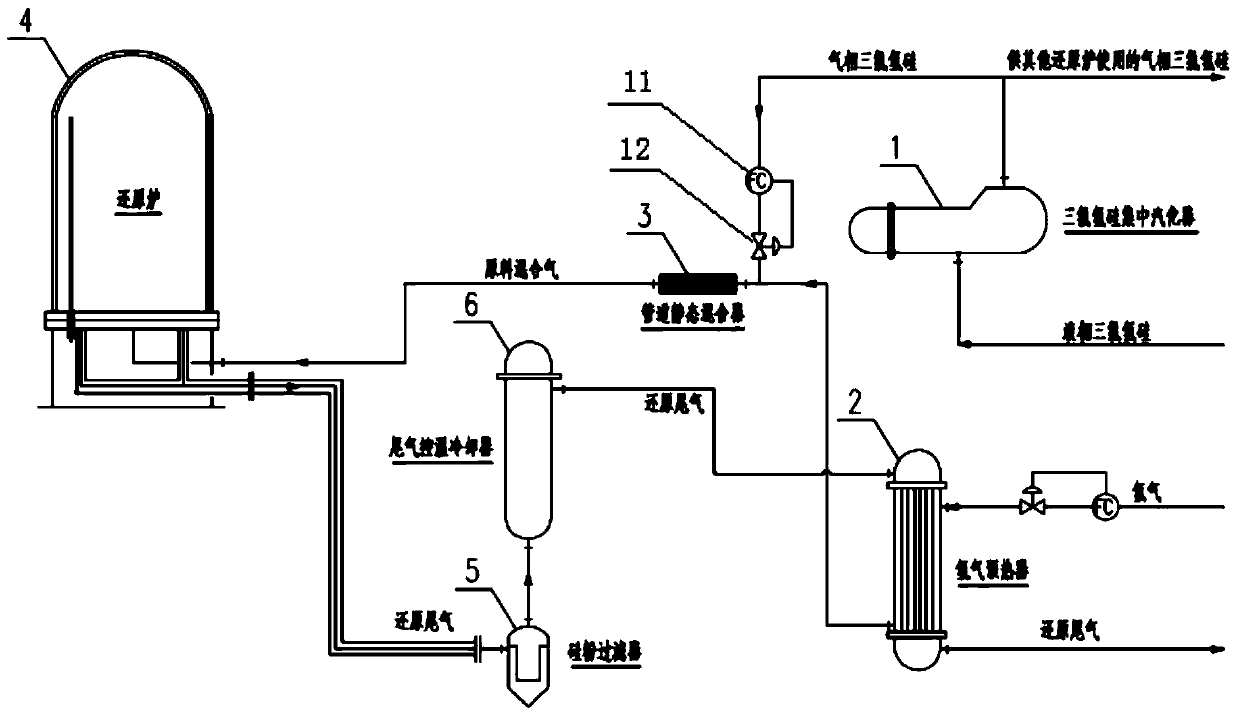
[0059] Example 1: The temperature control and energy-saving system for a polysilicon reduction furnace of the present invention includes a trichlorosilane centralized vaporizer 1, a hydrogen preheater 2, a pipeline static mixer 3, a reduction furnace 4, a silicon powder filter 5, and exhaust gas temperature control cooling 器6. The hot hydrogen outlet of the hydrogen preheater 2 tube side is connected to the pipeline static mixer 3, and the gas phase trichlorosilane outlet of the trichlorosilane centralized vaporizer 1 is connected to the hydrogen preheater 2 tube side The hot hydrogen outlet pipe is the smallest distance from the pipeline static mixer 3; the mixed gas outlet of the pipeline static mixer 3 is connected to the air inlet of the reduction furnace 4; the exhaust gas outlet of the reduction furnace 4 is connected to the silicon The inlet of the powder filter 5, the outlet of the silicon powder filter 5 is connected to the shell side high temperature gas phase inlet of...

Embodiment 2

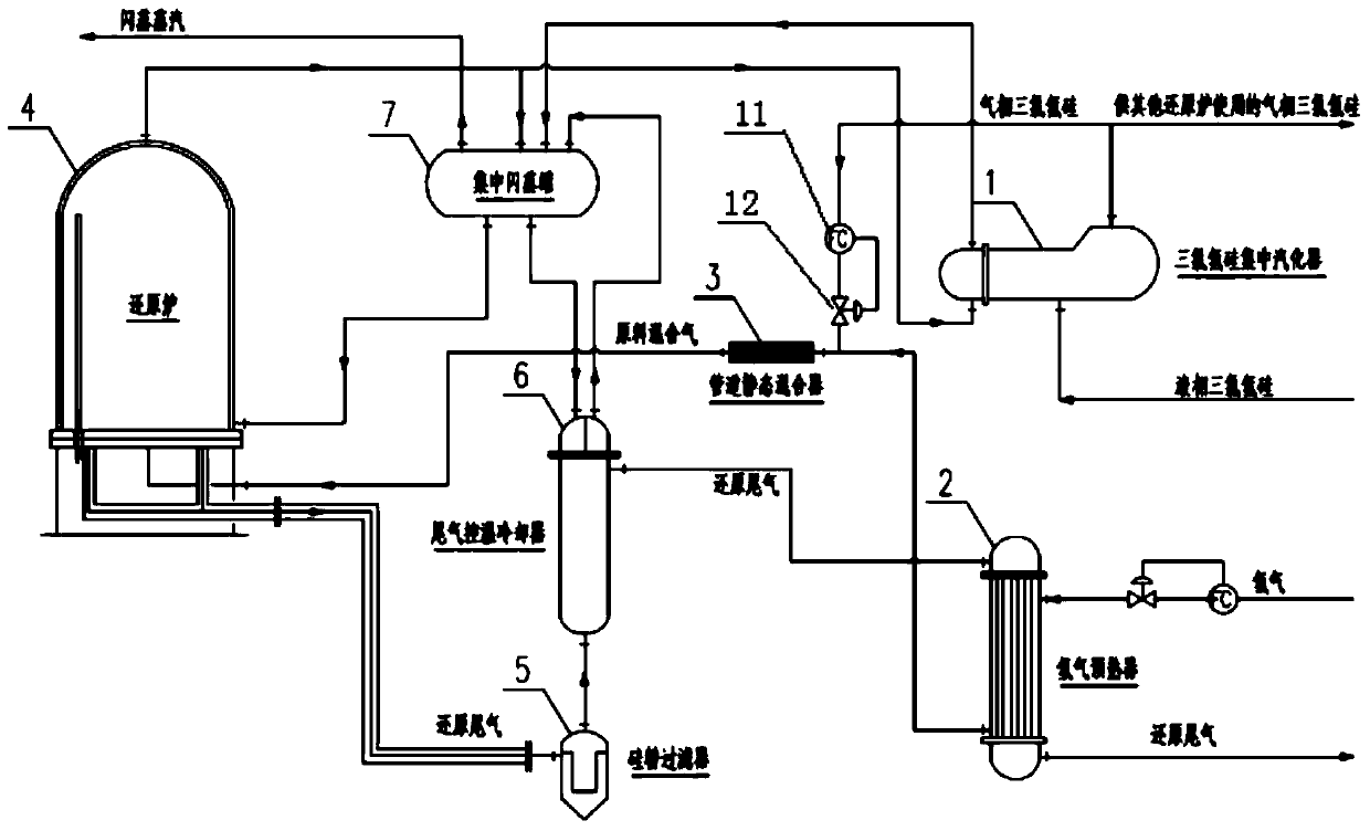
[0060] Embodiment 2: In a further improvement of this embodiment 1, a centralized flash tank 7 is also included. The centralized flash tank 7 has a furnace barrel cooling water outlet connected to the reduction furnace 4 furnace barrel cooling water inlet, and the reduction furnace 4 The furnace barrel cooling water outlet is connected to the centralized flash tank 7 furnace barrel cooling water return water inlet and the trichlorosilane centralized vaporizer 1 pipe pass inlet, and the trichlorosilane centralized vaporizer 1 pipe pass outlet is connected to the centralized vaporizer The flash tank 7 vaporizer return water inlet, the exhaust gas cooling water outlet of the centralized flash tank 7 is connected to the exhaust gas temperature control cooler 6 pipe pass inlet, and the exhaust gas temperature control cooler 6 pipe pass outlet is connected to the centralized flash tank 7 The exhaust cooling water return inlet.

[0061] The specific implementation method is that the tri...


PUM


Abstract

The invention discloses a temperature control and energy saving system and process for polycrystalline silicon reduction furnaces. The system is characterized by comprising a trichlorosilane concentrated carburetor, a hydrogen preheater, a pipeline static mixer, a reduction furnace, a silicon powder filter and a tail gas temperature-control cooler, wherein the hydrogen preheater 2 is connected to the pipeline static mixer 3, and the trichlorosilane concentrated carburetor is connected to a tube pass of the hydrogen preheater; the pipeline static mixer is connected to the reduction furnace; the tail gas outlet of the reduction furnace 4 is connected to the shell-pass high-temperature gas phase inlet of the tail gas temperature-control cooler, and the shell-pass low-temperature gas phase outlet of the tail gas temperature-control cooler is connected to the shell-pass gas phase inlet of the hydrogen preheater. According to the system and application method disclosed by the invention, feed compositions are uniform, the feed temperature is stable and controllable, the heat energy is used fully, the power consumption of the reduction furnace and the system is reasonably reduced, and the growth quality of polycrystalline silicon is controlled better; silicon powder of a tail gas pipeline is effectively removed, thereby protecting valves of the tail gas pipeline and facilities of a CDI (Capacitor Discharge Ignition) system.

Description

Technical field: [0001] The invention relates to a polysilicon production, in particular to a temperature control and energy-saving module system and process for a polysilicon reduction furnace, and belongs to the field of solar photovoltaic. Background technique: [0002] Since the 20th century, with the development of social economy and the improvement of people's living standards, the demand for energy has been increasing. The finite nature of fossil energy resources and their impact on the global climate and environment during the combustion process have attracted increasing attention. From the perspective of resource, environment, and social development needs, the development and utilization of new energy and renewable energy is an inevitable trend. In the new energy and renewable energy family, solar energy has become the most eye-catching member with the most research and application. With the rapid development of the solar energy industry, an investment boom in the poly...

Claims


Application Information

Patent Timeline
Patent Type & Authority Applications(China)
IPC IPC(8): C01B33/035
CPCY02P20/10
Inventor 陈宏伟许晟
Owner MORIMATSU (JIANGSU) HEAVY IND CO LTD
Why Eureka
Try Eureka