A flue gas desulfurization device and process
A desulfurization device and flue gas technology, applied to the separation of dispersed particles, chemical instruments and methods, separation methods, etc., to achieve the effects of stable operation, improved desulfurization rate and desorption rate, and convenient start and stop
- Summary
- Abstract
- Description
- Claims
- Application Information
AI Technical Summary
Problems solved by technology
Method used
Image
Examples
Embodiment 1
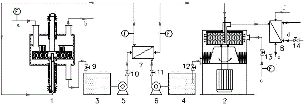
[0056] Example 1: Set the upper and lower turntables of the rotary packed bed absorber 1 to rotate in reverse, the speed is 400r / min, the concentration of sodium hydrogen phosphate buffered aqueous solution is 1mol / L (expressed as phosphate radical), the pH is 6.5, and the flue gas Medium SO 2 The concentration is 0.2%, and the flue gas flow rate is 150m 3 / h, the liquid-gas ratio is 0.8L / m3 , the absorption reaction temperature is 35°C, and the flue gas desulfurization rate is higher than 99.1%. The absorbed rich liquid is desorbed by the rotary packed bed desorber 2, the speed of the desorber is 600r / min, the temperature of the water vapor is 112°C, the temperature of the desorption operation is 97°C, and the gas-liquid ratio is 600m 3 / m 3 , the desorption rate of the rich solution is higher than 92%.
Embodiment 2
[0057] Example 2: Set the upper and lower turntables of the rotary packed bed absorber 1 to rotate in reverse, the speed is 600r / min, the concentration of the sodium phosphate buffer solution is 0.5mol / L (expressed as phosphate radical), the pH is 5.6, and the flue gas Medium SO 2 The concentration is 0.06%, and the flue gas flow rate is 120m 3 / h, the liquid-gas ratio is 0.6L / m 3 , the absorption reaction temperature is 35°C, and the flue gas desulfurization rate is higher than 99.3%. The absorbed rich liquid is desorbed by the rotary packed bed desorber 2, the speed of the desorber is 550r / min, the temperature of the water vapor is 109°C, the temperature of the desorption operation is 98°C, and the gas-liquid ratio is 500m 3 / m 3 , the desorption rate of the rich solution is higher than 93%.
Embodiment 3
[0058] Example 3: Set the upper and lower turntables of the rotary packed bed absorber 1 to rotate in reverse, the speed is 600r / min, the concentration of the sodium phosphate buffer solution is 1.5mol / L (expressed as phosphate radical), the pH is 6.0, and the flue gas Medium SO 2 The concentration is 1%, and the flue gas flow rate is 150m 3 / h, the liquid-gas ratio is 3L / m 3 , the absorption reaction temperature is 40°C, and the flue gas desulfurization rate is higher than 99.4%. The absorbed rich liquid is desorbed by the rotary packed bed desorber 2, the speed of the desorber is 800r / min, the temperature of water vapor is 115°C, the temperature of desorption operation is 97°C, and the gas-liquid ratio is 600m 3 / m 3 , the desorption rate of the rich solution is higher than 95%.
PUM
 Abstract
Description
Claims
Application Information
 - R&D
- Intellectual Property
- Life Sciences
- Materials
- Tech Scout
- Unparalleled Data Quality
- Higher Quality Content
- 60% Fewer Hallucinations
Browse by: Latest US Patents, China's latest patents, Technical Efficacy Thesaurus, Application Domain, Technology Topic, Popular Technical Reports.
© 2025 PatSnap. All rights reserved.Legal|Privacy policy|Modern Slavery Act Transparency Statement|Sitemap|About US| Contact US: help@patsnap.com


