
Rapid clamping device used for side milling and drilling of carbon fiber thin board

A clamping device and carbon fiber technology, applied in the direction of clamping device, positioning device, clamping, etc., can solve the problems of inability to correctly position the workpiece and cannot guarantee the processing quality, so as to improve production efficiency, reduce alignment time, clamp Even force distribution effect

Inactive Publication Date: 2014-01-08
JIMEI UNIV
View PDF8 Cites 22 Cited by
  • Summary
  • Abstract
  • Description
  • Claims
  • Application Information

AI Technical Summary

Problems solved by technology

Another example is the Chinese invention patent: a multi-point profiling rigid fixture and a method for processing thin-walled workpieces using the fixture. The publication number is: CN102179708A. This patent technology involves a multi-point profiling rigid The method for processing thin-walled workpieces, the fixture includes a fixture body, etc. The multi-point profiling rigid profiling fixture is used in the high-speed milling and finishing stage of complex profiles of thin-walled workpieces, but the positioning of the workpiece in this invention patent is only implemented through the surface of the fixture body , so that the workpiece cannot be positioned correctly, and the processing quality cannot be guaranteed; and the fixture is only used for side milling of thin-walled workpieces, without drilling process

Method used


Image

  • Rapid clamping device used for side milling and drilling of carbon fiber thin board
  • Rapid clamping device used for side milling and drilling of carbon fiber thin board
  • Rapid clamping device used for side milling and drilling of carbon fiber thin board

Examples


Embodiment Construction

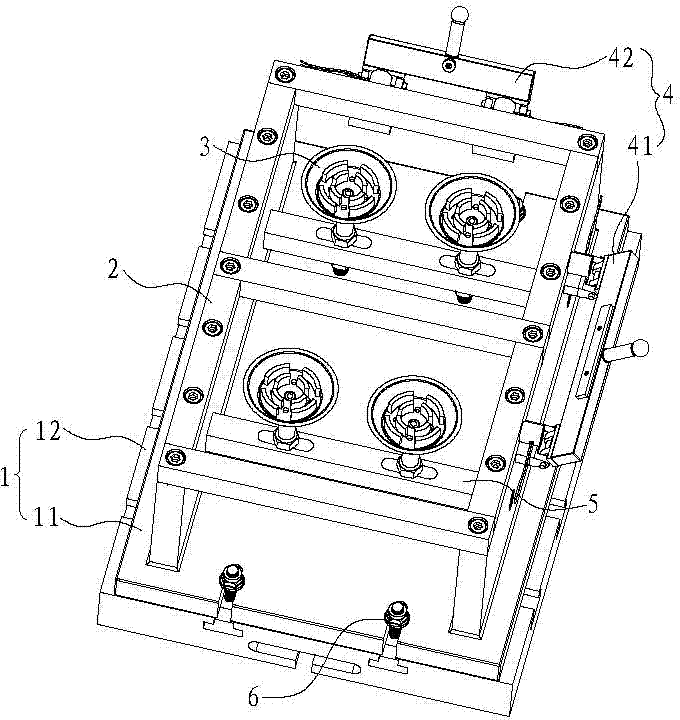
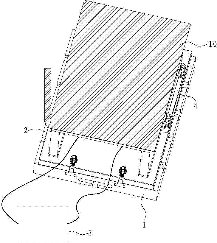
[0026] Such as figure 1 As shown, the present invention is a quick clamping device for side milling and drilling of carbon fiber thin plates. Component 6.

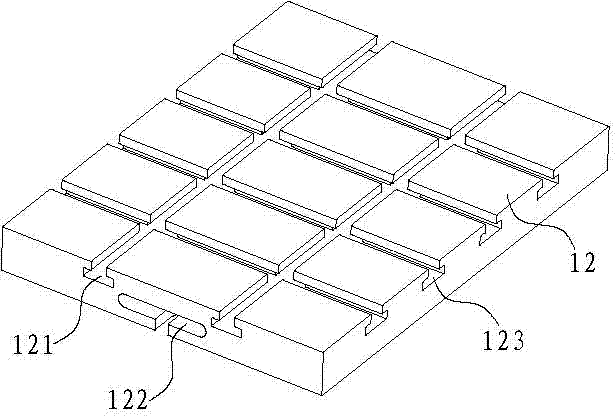
[0027] The clamp body 1 is composed of a clamp body 11 and a clamp body base 12 . to combine image 3 As shown, the clamp body base 12 is provided with front and rear T-shaped grooves 121, U-shaped grooves 122, and left and right T-shaped grooves 123, and the clamp body 1 is fixed on the machine tool workbench by T bolts. The clamp body base 12 is fixed on the machine tool through a T-shaped connecting block, and the fastener assembly 6 fixes the clamp body 11 on the clamp body base 12 . The positioning frame 2 is fixed on the top surface of the clamp body 11 of the clamp body 1 .

[0028] The positioning frame 2 is a rectangular frame.

[0029] The positioning member 4 is composed of left and right magnetic positioning strips 41 and front and rear magnetic positioning blocks 42 . The left and right magnetic positio...


PUM


Abstract

The invention discloses a rapid clamping device used for side milling and drilling of a carbon fiber thin board. The rapid clamping device comprises a clamping device body, a locating frame, a plurality of vacuum sucker assemblies and a locating part; the clamping device body is fixed to a machine tool through a bolt, the locating frame is fixed to the top surface of the clamping device body, and the vacuum sucker assemblies are arranged in the locating frame and are connected with a vacuum pump through pipelines; the locating part is hinged to the side edge of the locating frame in a vertical swing mode, the carbon fiber thin board can be completely located through the locating frame and the locating part, the locating frame is fixedly connected with the clamping device body, the locating part is hinged to the clamping device body, and the locating part turns around the axis of a pin. One-time clamping can achieve milling of the side faces of the periphery of a workpiece, and cutting efficiency is greatly improved; the vacuum sucker assemblies can move to regulate the positions on a long kidney-shaped hole supporting transverse beam, and drilling of different positions of the carbon fiber thin board can be conveniently conducted. Therefore, the rapid clamping device has the advantages of being rapid in locating, reliable in clamping, adjustable in drilling position, simple in tool, high in production efficiency and the like.

Description

technical field [0001] The invention relates to a carbon fiber thin plate side milling and drilling processing technology, in particular to a quick clamping device for carbon fiber thin plate side milling and drilling. Background technique [0002] Carbon fiber composite material (CFRP) is a composite material with carbon fiber as a reinforcing material and resin as a matrix. Because of its high specific strength and specific stiffness, good fatigue resistance, and good temperature resistance, it is widely used in the aerospace field. , and has rapidly developed into one of the four major aerospace structural materials after aluminum, steel, and titanium, and drilling and milling are an extremely important process in the processing technology of carbon fiber composite parts. [0003] To improve the processing quality and production efficiency of carbon fiber sheet, the reasonable design of tooling is particularly important. Usually, tooling needs to be designed and manufactu...

Claims


Application Information

Patent Timeline
IPC IPC(8): B23Q3/08
CPCB23Q3/062B23Q3/088B23Q2703/04B23Q2703/10
Inventor 许志龙程龙杨星杨小璠刘菊东侯达盘吴碧金鄢国洪李友生
Owner JIMEI UNIV
Features
  • Generate Ideas
  • Intellectual Property
  • Life Sciences
  • Materials
  • Tech Scout
  • Unparalleled Data Quality
  • Higher Quality Content
  • 60% Fewer Hallucinations
Learn More