Flat tube type solid oxide fuel cell pack

A technology of solid oxide and fuel cell stacks, which is applied in the direction of solid electrolyte fuel cells, fuel cell groups, fuel cells, etc. It can solve the problems of large airflow resistance, gas utilization rate and battery performance degradation, and achieve easy assembly and compact structure , The effect of high current collection efficiency

Active Publication Date: 2014-01-15
DALIAN INST OF CHEM PHYSICS CHINESE ACAD OF SCI
View PDF3 Cites 10 Cited by
  • Summary
  • Abstract
  • Description
  • Claims
  • Application Information

AI Technical Summary

Problems solved by technology

The flat-plate design has the advantages of short current collection paths, high power density, and simple fabrication process; however, this design has a major disadvantage: the need to seal the flat-plate ceramic components to obtain the required airtightness when forming the stack to avoid direct contact between fuel gas and oxygen-containing gas
When the planar area of ​​the flat tube battery unit is large, due to the narrow gap between the cells and the large airflow resistance, the relatively wide space outside the battery pack will become the main flow channel of the gas, and only a small amount of gas can enter the gap between the cells and Participate in the reaction, the gas utilization rate and battery performance are significantly reduced

Method used


Image

  • Flat tube type solid oxide fuel cell pack
  • Flat tube type solid oxide fuel cell pack
  • Flat tube type solid oxide fuel cell pack

Examples


Embodiment 1

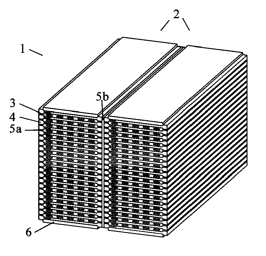
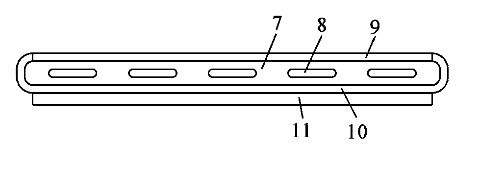
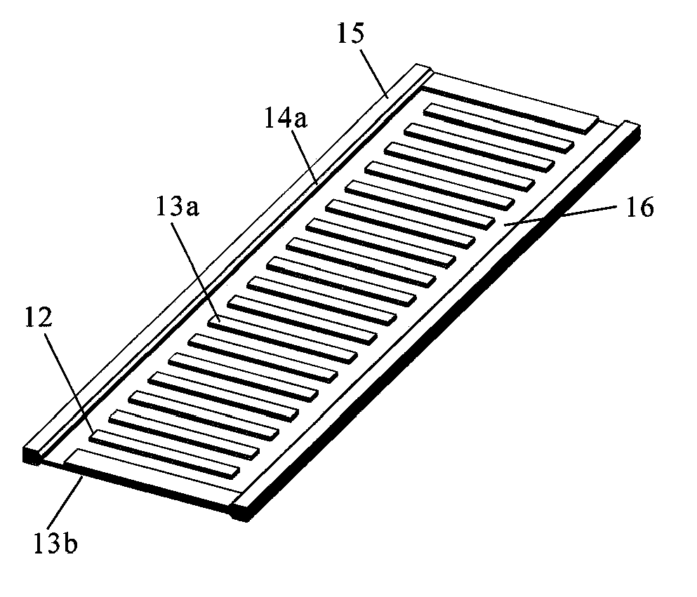
[0029] figure 1 It is a perspective view showing an embodiment of a flat-tube SOFC stack. figure 2 is a schematic diagram of the fuel cell unit structure, image 3 yes figure 1 Schematic diagram of the connected components in the middle cell stack.

[0030] Such as figure 1 As shown, the flat tube SOFC battery stack 1 in this embodiment is composed of two battery packs 2 placed side by side. Each battery pack includes a plurality of alternately placed fuel cell units 3 , connecting parts 4 and insulating materials 5 a between the connecting parts. Collector end plates 6 are arranged at both ends of the battery pack, and current is drawn through the collector end plates for use by external loads. According to the requirements of the load, the battery packs can be connected in series or in parallel (not shown in the figure). In order to prevent a short circuit between the battery packs, an insulating material 5b is provided between the two battery packs. Insulating mater...

Embodiment 2

[0040] Such as Figure 6 As shown, the difference from Embodiment 1 is that on the plate-shaped alloy connection part 4 constituting the flat tube type SOFC battery pack 2, a plurality of short rectangular bosses 12 are set, and between the plurality of short rectangular bosses Formed cross-distributed longitudinal and transverse gas flow channels, making the flow field distribution more uniform.

Embodiment 3

[0042] Such as Figure 7 As shown, the difference from Example 1 is that a plurality of V-shaped bosses 12 are arranged on the plate-shaped alloy connection part 4 constituting the flat-tube SOFC battery pack 2, which can effectively disturb the flow field of the air. And the formation of turbulent flow is conducive to increasing the concentration of reaction gas on the surface of the external electrode and enhancing mass transfer. In addition, in this embodiment, the supporting electrode 7 is a cathode, the external electrode 9 is an anode, and the insulating material 5a uses a glass-ceramic sealing material to obtain the required airtightness. In this embodiment, the plate-shaped alloy substrate 1 uses a Ni-Cr alloy with a brand name of Inconel625, without pre-oxidation and coating treatment.


PUM

PropertyMeasurementUnit
thicknessaaaaaaaaaa

Abstract

The invention discloses a flat tube type solid oxide fuel cell pack, which comprises more than two flat tube type fuel cell units that are connected by plate alloy connecting components. The substrate of the plate alloy connecting components is a Cr-containing Fe based or Ni based alloy, the surface of which is coated with a conductive coating inhibiting alloy high temperature oxidation and Cr pollution. The plate alloy connecting components are provided with arc-shaped grooves or bent surfaces matching with arc surfaces on both sides of the flat tube type cell units. During formation of the cell pack, the arc-shaped grooves or bent surfaces cooperate with the fuel cell units to form independent gas flow channels and make the solid fuel cell units fixed. Over two fuel cell units and the plate alloy connecting components are alternately arranged to form the cell pack with a rectangular cross section. The flat tube type solid oxide fuel cell pack can introduce a reaction gas into the narrow space between the flat tube type fuel cell units, and a fuel cell stack with a compact structure is easy to form by close piling. The flat tube type solid oxide fuel cell pack has the advantages of good power generation performance, compact structure and high stability, etc.

Description

technical field [0001] The invention relates to a solid oxide fuel cell, in particular to a flat tube type solid oxide fuel cell stack. Background technique [0002] A solid oxide fuel cell (SOFC) is a power generation device that directly converts chemical energy in fuel into electrical energy in a clean and efficient manner. Under the working temperature environment, fuel gas and oxygen-containing gas are supplied to the anode and cathode respectively, and the battery can provide voltage, and the battery can output electric energy after being connected to the load. Due to the low voltage and power of fuel cell units, in actual use, multiple fuel cell units are often connected in series or parallel in a certain way to form a battery pack to meet actual power supply requirements. [0003] At present, there are three main forms of SOFC single cells: flat plate, tube and flat tube. The flat-plate design has the advantages of short current collection paths, high power density...

Claims


Application Information

Patent Timeline
Patent Type & Authority Applications(China)
IPC IPC(8): H01M8/10H01M8/24H01M8/04H01M8/2465
CPCH01M8/0273H01M8/04201H01M8/249Y02E60/50
Inventor 区定容程谟杰
Owner DALIAN INST OF CHEM PHYSICS CHINESE ACAD OF SCI
Why Eureka
Try Eureka