
Device and method for ultrasonic tank demulsification

An ultrasonic and demulsification technology, which is applied in the direction of electric/magnetic dehydration/demulsification, separation of immiscible liquids, chemical/physical/physicochemical processes using energy, etc., can solve the problems affecting the normal progress of sewage treatment and standard discharge Problems such as rising oil content and COD value in drainage, inconvenient inspection and maintenance, etc., to achieve the effect of mobile detachable, easy maintenance, installation and disassembly

Active Publication Date: 2015-08-19
CHINA PETROLEUM & CHEM CORP
View PDF5 Cites 0 Cited by
  • Summary
  • Abstract
  • Description
  • Claims
  • Application Information

AI Technical Summary

Problems solved by technology

Over the years, the research on crude oil demulsification technology is mostly limited to the research of chemical demulsifiers, which has great limitations on different types of crude oil, and the application of demulsifiers has many production and environmental problems: resulting in increased production costs, resulting in The oil content and COD value of the drainage will increase, which will directly affect the normal operation and standard discharge of subsequent sewage treatment
The device is directly refitted to the tank to be treated or the settling tank. Since the upper head of the tank to be treated or the settling tank is a convex structure, the defect is that the ultrasonic transducer needs a long horn length to extend into the demulsification tank. , which directly affects the electro-acoustic efficiency, the ultrasonic waves generated by the ultrasonic distributor cannot effectively affect the oil-water emulsion; when the device is used, it needs to be temporarily refitted to treat the tank or the settling tank to install multiple ultrasonic generators
The ultrasonic distributor directly acts on the oil-water emulsion to cause dead angle or short circuit phenomenon. The equipment structure is complicated, the inspection and maintenance are inconvenient, the manufacturing cost is high, and the reusability is poor.

Method used


Image

  • Device and method for ultrasonic tank demulsification
  • Device and method for ultrasonic tank demulsification
  • Device and method for ultrasonic tank demulsification

Examples


Embodiment 1

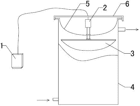
[0032] Such as figure 1 As shown, the head of the top cover 5 of the demulsification tank is installed in a concave manner, and the ultrasonic transducer 2 is connected to the inside of the tank using a conventional connection method, welding or flange compression connection, and the top of the tank is to prevent rain accumulation Water, the rainproof cover plate 6 is set. A single set of ultrasonic transducer distribution device is installed in the demulsification tank 4, and the single set of ultrasonic transducer distribution device is only installed on the top of the demulsification tank. The ultrasonic generator 1 is installed in an explosion-proof control cabinet, and the ultrasonic generator 1 is connected with the ultrasonic transducer 2 through a power cable.

[0033] The lower part of the ultrasonic distributor 3 is stamped with a thin steel plate to form a head-type structure, and the upper part of the ultrasonic distributor 3 is provided with a rainproof cover 6 m...

Embodiment 2

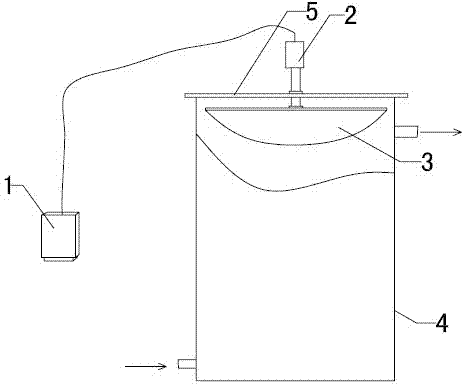
[0037] Such as figure 2 The top cover 5 of the demulsification tank of the ultrasonic tank type demulsification device shown is a flat head, and other devices are the same as in Embodiment 1.

[0038] The feed port of the ultrasonic tank demulsifier is connected to the crude oil pipeline with 1.5% water content. At 20°C, the ultrasonic frequency is 40kHz, and the ultrasonic sound intensity is 0.3 w / cm 2 . Transported by the crude oil pump, the water-containing crude oil passes through the feed port at a speed of 2m 3 / min. It enters from the lower part of the demulsification tank through the pipeline, and after the tank-type demulsification effect of a single set of ultrasonic transducers and ultrasonic distributors, it is exported from the top of the demulsification tank and introduced into the sedimentation dehydration tank to complete the oil-water separation process. After settling in the settling dehydration tank for 48 hours, the water content of the dirty oil in the...

Embodiment 3

[0040] The device used is the same as in Example 1.

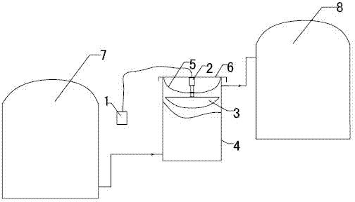
[0041] Install a set of top cover concave type ultrasonic tank demulsification device of the present invention between the dirty oil storage tanks with water content of 7.0%. At 80°C, the ultrasonic frequency is 200kHz, and the ultrasonic sound intensity is 0.1 w / cm 2 . Transported by the crude oil pump, the water-containing sewage oil passes through the feed port at a speed of 2m 3 / min. It enters from the lower part of the demulsification tank through the pipeline, and after the tank-type demulsification effect of a single set of ultrasonic transducers and ultrasonic distributors, it is exported from the top of the demulsification tank and introduced into the sedimentation dehydration tank to complete the oil-water separation process. After settling in the settling dehydration tank for 48 hours, the water content of the dirty oil in the tank was reduced to 1.4%.


PUM


Abstract

The invention discloses an ultrasonic wave tank type demulsification device and method. The device is provided with a demulsification tank, wherein the top of the demulsification tank is of an inwards-concave type structure or flat plate type structure, an ultrasonic generator arranged in an anti-explosion cabinet controls an ultrasonic transducer, ultrasonic energy provided by one set of ultrasonic transduction distribution device is re-distributed through an ultrasonic distributor, the ultrasonic generator is arranged in the demulsification tank, a homogeneous liquid is filled in the demulsification tank, an oil-water emulsion enters from the lower part of the tank and flows out from the upper part of the tank after being subjected to the action of ultrasonic waves. The method and device are good in ultrasonic action and contact effect, simple in internal structure and convenient to install, are suitable for demulsifying the oil-water emulsion, and especially suitable for tank type demulsification and dewatering in an oil field or oil refinery.

Description

technical field [0001] An ultrasonic tank-type demulsification device and method belong to the field of petrochemical technical equipment. Background technique [0002] In recent years, with the gradual reduction of petroleum resources and the continuous increase of people's demand for petroleum products, oilfield companies have been prompted to adopt various measures to increase production, using crude oil reserves that were difficult to exploit in the past, and widely applying tertiary oil recovery technologies, such as polymer flooding, multi-component compounding, etc. The extensive application of technologies such as flooding, surface active flooding, alkali flooding, carbon dioxide flooding, and thermal recovery of heavy oil has resulted in intensified emulsification of heavy and inferior crude oil and stable emulsified structure. It is difficult to quickly achieve effective emulsification by traditional thermochemical means. The purpose of oil-water separation. [00...

Claims


Application Information

Patent Timeline
Patent Type & Authority Patents(China)
IPC IPC(8): B01D17/04B01J19/10C10G33/02
Inventor 苟社全张红宇张义玲常文之许金山刘爱华张传明梁颖杰崔云梓
Owner CHINA PETROLEUM & CHEM CORP
Learn More