Piezoelectric and triboelectric coupling-based flexible micro energy harvester and preparation method

An energy harvester and triboelectric technology, applied in the device field of the energy technology field, can solve the problems of high processing cost, high vibration frequency, and reduce the resonance frequency of the energy harvester, and achieve easy miniaturization and array, easy mass production, The effect of broadening the scope of application

Active Publication Date: 2014-01-22
SHANGHAI JIAO TONG UNIV
View PDF6 Cites 30 Cited by
  • Summary
  • Abstract
  • Description
  • Claims
  • Application Information

AI Technical Summary

Problems solved by technology

[0003] At present, most of the piezoelectric energy harvesters prepared by MEMS technology are rigid structures, and the collected vibration frequency is relatively high.
At the same time, the current miniature electrostatic energy harvester adopts silicon-based technology, which requires large-scale equipment and special processes, and the processing cost is too hig

Method used


Image

  • Piezoelectric and triboelectric coupling-based flexible micro energy harvester and preparation method

Examples


Embodiment 1

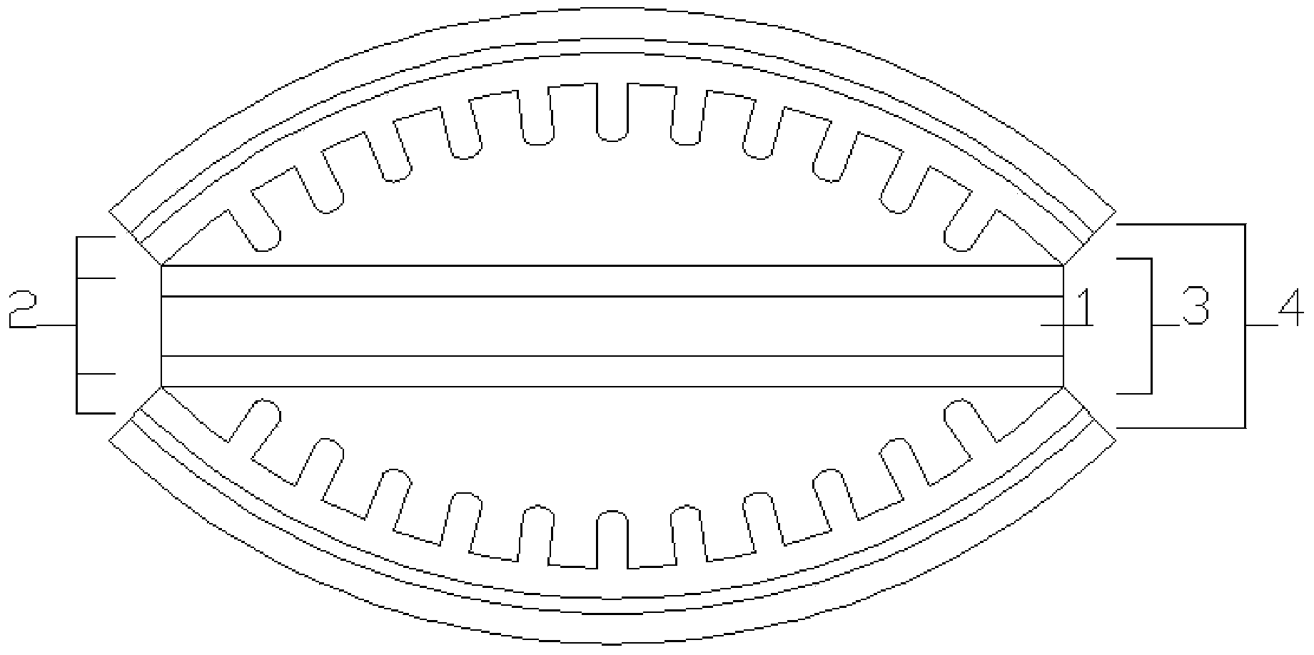
[0036] Such as figure 1 As shown, the flexible micro energy harvester based on piezoelectric and triboelectric coupling disclosed in the present invention includes: a piezoelectric layer 1 , an electrode layer 2 , a friction layer 3 , and a substrate layer 4 . The piezoelectric layer is fabricated on a flexible PET (polyethylene terephthalate) film with an electrode layer of ITO (indium tin oxide) by spin coating or electrospinning, and then PDMS (polyethylene terephthalate) with a bump structure Dimethylsiloxane) friction layer is symmetrically attached to the piezoelectric layer with metal electrodes, and finally the PET substrate of the ITO electrode layer is symmetrically bonded to the electrostatic friction layer PDMS.

[0037] The piezoelectric layer includes P(VDF-TrFE) piezoelectric material, the electrode layer is ITO, the electrostatic friction layer is PDMS and PET with a bump structure, and the substrate layer includes PET.

Embodiment 2

[0039] Such as figure 1 As shown, the flexible micro energy harvester based on piezoelectric and triboelectric coupling disclosed in the present invention includes: a piezoelectric layer 1 , an electrode layer 2 , a friction layer 3 , and a substrate layer 4 . On the electrode layer Al, Cu or Au foil, the piezoelectric layer is made by spin coating or electrospinning, and then the friction layer, that is, the PDMS with a bump structure, is pressed symmetrically on the upper and lower electrode layers of the piezoelectric layer, and finally with The PET substrate of the ITO electrode layer is symmetrically bonded on the friction layer PDMS.

[0040] The piezoelectric layer includes PVDF (polyvinylidene fluoride) piezoelectric material, the electrode layer is Al, Cu, Au foil and ITO, the electrostatic friction layer is PDMS with a bump structure, and the substrate layer includes PET.

[0041]Under the influence of the outside world on the micro-energy harvester, the energy harv...


PUM


Abstract

The invention discloses a piezoelectric and triboelectric coupling-based flexible micro energy harvester. The energy harvester comprises a piezoelectric layer, first electrode layers, second electrode layers, friction layers and substrate layers, wherein the first electrode layers, the friction layers, the second electrode layers and the substrate layers are arranged on the upper and lower sides of the piezoelectric layer from inside to outside in sequence; the friction layers comprise bumps with micron-scale structures. The invention also provides a corresponding preparation method. Each metal electrode layer and each metal compound layer are obtained from flexible piezoelectric materials such as PVDF (Polyvinylidene Fluoride) obtained through a spin coating, deposition or electrostatic spinning process by using processes such as sputtering, spin coating and evaporation, the flexible polymer bump static friction layer is prepared by using a molding method, meanwhile, a flexible substrate polymer is adopted and a piezoelectric and triboelectric principle is combined to manufacture the micro energy harvester of a hamburger structure stacked by central piezoelectric layers. The device has the characteristics of simple structure, easiness in implementation of micro machining, variable size, wide frequency band, high conversion efficiency and the like.

Description

technical field [0001] The invention relates to a device in the field of energy technology, and more specifically, relates to a piezoelectric and triboelectric coupling flexible miniature energy harvester and a preparation method thereof. Background technique [0002] In recent years, with the rapid development of micromachining technology and wireless sensing technology, new requirements and challenges have been put forward for the performance and application range of micro energy harvesters. The micro-vibration energy harvester based on static electricity and piezoelectricity, as a new type of self-powered micro-energy device, can convert the deformation of the energy harvester in the environment into electrical energy through the piezoelectric effect, and at the same time use friction to generate energy. Triboelectricity is generated by the principle of electricity and electrostatic induction, which is provided to microelectronic devices, and has received more and more ex...

Claims


Application Information

Patent Timeline
IPC IPC(8): H02N2/18H02N1/04B32B3/30
Inventor 杨斌王兴昭刘景全朱红英杨春生
Owner SHANGHAI JIAO TONG UNIV
Why Eureka
Try Eureka