Microwave high-frequency metal matrix circuit board

A high-frequency metal, circuit substrate technology, applied in the direction of circuit substrate materials, printed circuit components, etc., can solve the problems of overheating of components on the circuit board, decreased reliability of the whole machine, easy falling off or breaking of the circuit layer of the circuit board, etc. Achieve excellent heat dissipation performance, reduce processing costs, and achieve good heat dissipation effects

Inactive Publication Date: 2014-01-22
朱云霞
View PDF0 Cites 2 Cited by
  • Summary
  • Abstract
  • Description
  • Claims
  • Application Information

AI Technical Summary

Problems solved by technology

[0002] With the development of high-power, high-density electronic devices and the continuous advancement of electronic technology, electronic products are developing towards light, thin, small, and multi-functional. Traditional circuit substrates are gradually replaced by high-speed, high-reliability high-frequency circuits. Substrate replacement, polytetrafluoroethylene glass cloth copper clad board is favored by customers in high-frequency circuit substrates due to its low dielectric, low dielectric loss, low water absorption, and wide temperature range. It can carry large current and high power. The high-frequency metal-based circuit substrate has been widely used, and the heat dissipation problem of electronic devices on the circuit board has become increasingly prominent. The bonding of thicker copper foil and the dielectric layer, the anti-peel strength is the key, and the bonding sheet technology is very important for the metal substrate and The bonding force between the copper foil layers and the peel strength after the formation of the circuit layer play a vital role. The peel strength index after thermal stress is not less than 1.05N / mm, which has always been a key index that plagues the production of this substrate , because the polytetrafluoroethylene glass cloth copper-clad laminate dielectric material polytetrafluoroethylene resin (PTFE) has a layer of fluorine-containing shell outside the molecule, which has outstanding non-stick performance. After being applied in a high heat-resistant environment, the circuit board circuit Layers are easy to fall off or break, causing overheating of components on the circuit board, thereby reducing the reliability of the whole machine

Method used


Image

  • Microwave high-frequency metal matrix circuit board

Examples


Embodiment Construction

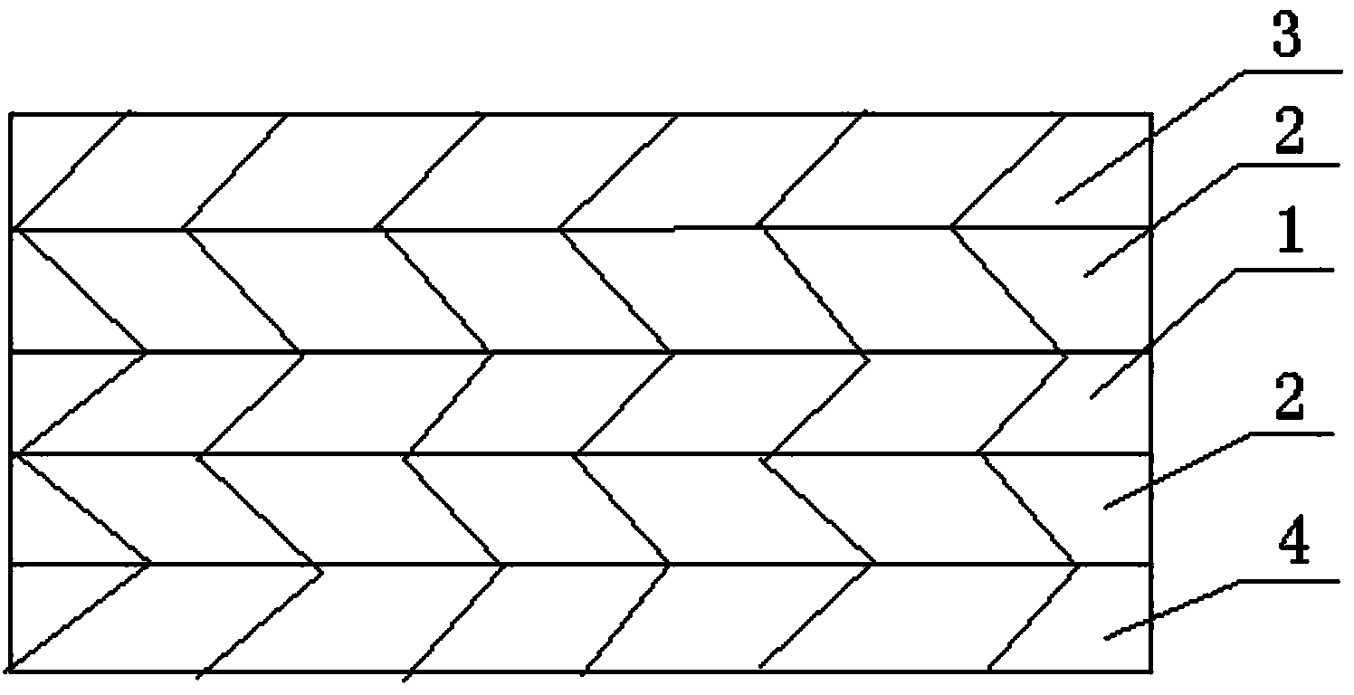
[0008] Such as figure 1 As shown, the present invention provides a microwave high-frequency metal-based circuit substrate, including a metal-based substrate 3, and the metal-based substrate 3 is any one of aluminum, aluminum alloy, copper, copper alloy, and stainless steel. One side of the substrate 3 is sequentially provided with an insulating dielectric material layer 1 and a copper foil layer 4, the thickness of the copper foil layer 4 is 35um-280um, and the metal-based substrate 3 and the insulating dielectric material layer 1 are bonded by the bonding sheet 2, so The insulating dielectric material layer 1 and the copper foil layer 4 are bonded by an adhesive sheet 2. The insulating dielectric material layer 1 is formed by ball milling polytetrafluoroethylene powder and polyphenylene ether powder and then pressed together. The adhesive sheet 2 It is a bonding sheet formed by PTFE dispersion liquid and glass cloth impregnated with glue.


PUM


Abstract

The invention discloses a microwave high-frequency metal matrix circuit board, comprising a metal matrix circuit board (3); an insulation medium material layer (1) and a copper foil layer (4) are sequentially arranged at one surface of the metal matrix circuit board (3); the metal matrix circuit board (3) is bonded with the insulation medium material layer (1) by one bonding sheet (2); the insulation medium material layer (1) and the copper foil layer (4) are bonded by one bonding sheet (2); the insulation medium material layer (1) is formed by laminating and mixing teflon powder and polyphenyl ether in a ball-milling mode; the bonding sheets (2) are formed by gum dipping of teflon dispersion liquid and woven glass fabric. The microwave high-frequency metal matrix circuit board has the advantages such as simple structure, good insulation property, low heat resistance, high heat conduction, excellent radiating property, stable and reliable performances, low manufacturing cost and usability under a high-humidity high-temperature environment for a long time.

Description

technical field [0001] The invention relates to a circuit board, in particular to a high-frequency metal-based circuit substrate. Background technique [0002] With the development of high-power, high-density electronic devices and the continuous advancement of electronic technology, electronic products are developing towards light, thin, small, and multi-functional. Traditional circuit substrates are gradually replaced by high-speed, high-reliability high-frequency circuits. Substrate replacement, polytetrafluoroethylene glass cloth copper clad board is favored by customers in high-frequency circuit substrates due to its low dielectric, low dielectric loss, low water absorption, and wide temperature range. It can carry large current and high power. The high-frequency metal-based circuit substrate has been widely used, and the heat dissipation problem of electronic devices on the circuit board has become increasingly prominent. The bonding of thicker copper foil and the diel...

Claims


Application Information

Patent Timeline
Patent Type & Authority Applications(China)
IPC IPC(8): H05K1/05
Inventor 朱云霞
Owner 朱云霞
Why Eureka
Try Eureka