
A Magnetic Suspension Supporting Structure of a Linear Feed Unit

A technology of linear feed and support structure, applied in the direction of electrical components, propulsion systems, magnetic attraction or thrust holding devices, etc., can solve the problem of reducing the effective support of the guide rail, affecting the processing and control accuracy of the feed unit, and reducing the rigidity of the guide rail structure and other problems, to achieve the effect of resisting adverse effects, improving processing accuracy and control accuracy, and reducing processing difficulty

Active Publication Date: 2015-09-23
南通大学技术转移中心有限公司
View PDF8 Cites 1 Cited by
  • Summary
  • Abstract
  • Description
  • Claims
  • Application Information

AI Technical Summary

Problems solved by technology

The mobile platform adopts a rectangular frame structure, which can resist the adverse effect of the guiding force on the rigidity of the workbench to a certain extent, but the length of the guide rail is limited to limit the stroke of the linear motion, otherwise the effective support of the base to the guide rail will be greatly reduced, reducing the The structural rigidity of the guide rail itself affects the processing and control accuracy of the feed unit
[0008] Jing Minqing and others published "Research on Two-Dimensional High-precision Magnetic Suspension Positioning Platform" in "Journal of Xi'an Jiaotong University", Duan Ji'an and others published "A New Type of Magnetic Suspension Linear Motion Platform" in "Chinese Journal of Electrical Engineering" "Thermal Analysis" and "Modal Analysis of Magnetic Levitation Linear Motion Platform" published by Guo Ningping and others in "Journal of Engineering Design" and other articles, the maglev linear feed unit did not take any measures for the adverse effect of the guiding force on the stiffness of the worktable. efficient design

Method used


Image

  • A Magnetic Suspension Supporting Structure of a Linear Feed Unit
  • A Magnetic Suspension Supporting Structure of a Linear Feed Unit
  • A Magnetic Suspension Supporting Structure of a Linear Feed Unit

Examples


Embodiment Construction

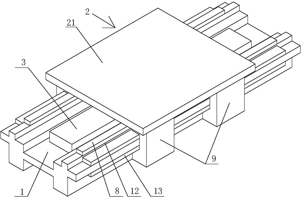
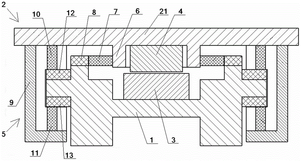
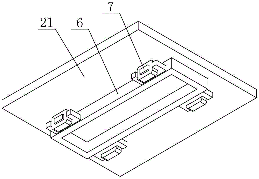
[0029] The present invention will be further described below in conjunction with the accompanying drawings and specific embodiments.

[0030] Such as Figures 1 to 4 As shown, the magnetic levitation support structure of the linear feed unit in this embodiment includes: a bed guide rail 1 fixed on the base, a workbench 2 set on the bed guide rail 1, and a linear motor stator 3 is installed on the bed guide rail 1 , the relative position of the workbench 2 is equipped with a linear motor mover 4 that cooperates with the linear motor stator 3, and the workbench 2 is composed of an upper workbench 21 and a supporting device 5 installed below the four corners of the upper workbench 21. The central position of the lower surface of the workbench 21 has a downwardly protruding rigid rectangular frame 6 arranged longitudinally (the rectangular frame 6 and the upper workbench 21 are integrally made of magnetically isolated aluminum material). The outer diameter of the rectangular frame...


PUM


Abstract

The invention relates to a magnetic suspension supporting structure of a straight feeding unit. A workbench of the magnetic suspension supporting structure consists of an upper workbench and a supporting device and operates along guide rails of a machine body; the central position of the lower surface of the upper workbench is provided with a rigid rectangular frame which is protruded downward and is distributed along the longitudinal direction; the left and right sides of the rectangular frame are symmetrically and horizontally provided with two guide electric magnets; the stress of the guide electric magnets in the horizontal direction is conveyed to the upper workbench by virtue of the rectangular frame; the guide rails of the machine body are provided with guide armature irons matched with the guide electric magnets; the supporting device comprises a support column, an upper supporting electric magnet and a lower supporting electric magnet; the guide rails of the machine body are provided with an upper supporting armature iron and a lower supporting armature iron. The magnetic suspension supporting structure is reasonable in structure and convenient to implement, can be used for performing long-stroke effective magnetic suspension supporting and guiding of the workbench, obviously enhancing the interference capability of anti-guiding external force against the rigidity of the workbench, reducing the coupling of magnetic fields and reducing the processing and control difficulty of the magnetic suspension straight feeding unit, and is applicable to a high-precise efficient numerically-controlled machine.

Description

technical field [0001] The invention relates to a linear feed unit, in particular to a magnetic suspension support structure of the linear feed unit. Background technique [0002] The industry is changing with each passing day, and the modern manufacturing industry has higher and higher requirements for the processing accuracy and efficiency of processing equipment, which promotes the development of the machine tool industry, especially the CNC machine tools. However, the industrial scale and product level of the functional components supporting the CNC machine tool are far from meeting the development requirements of the CNC machine tool. The feed unit is an important functional part of the CNC machine tool. The final coordinates and contour accuracy of the processed workpiece are affected by the transmission accuracy, sensitivity and stability of the feed unit movement. Therefore, it must have small frictional resistance, high transmission accuracy, It has the characteris...

Claims


Application Information

Patent Timeline
Patent Type & Authority Patents(China)
IPC IPC(8): B23Q1/25H02N15/00H02K41/02
CPCB23Q5/34H02K41/02H02N15/00
Inventor 肖龙雪吴国庆吴树谦朱维南茅靖峰张旭东张玉梅
Owner 南通大学技术转移中心有限公司
Learn More