Measurement and control system capable of isolating strong impulse interference

A technology of measurement and control system and strong pulse, applied in the field of measurement and control system, can solve problems such as test system damage, and achieve the effect of reducing damage, low cost and reducing range

Active Publication Date: 2014-02-12
DALIAN INST OF CHEM PHYSICS CHINESE ACAD OF SCI
View PDF5 Cites 6 Cited by
  • Summary
  • Abstract
  • Description
  • Claims
  • Application Information

AI Technical Summary

Problems solved by technology

It is found that about ±100V AC signal is coupled into the wire, if the interference signal is not suppressed, it will cause dam

Method used


Image

  • Measurement and control system capable of isolating strong impulse interference
  • Measurement and control system capable of isolating strong impulse interference
  • Measurement and control system capable of isolating strong impulse interference

Examples


Example Embodiment

[0024] Example 1

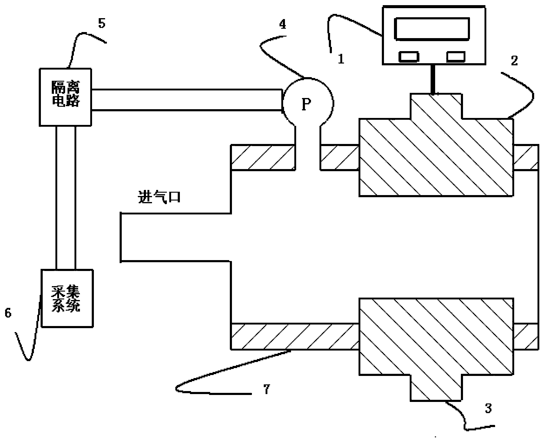
[0025] Such as figure 1 As shown, a measurement and control system that can isolate strong pulse interference is used for a high-energy pulsed gas laser with a pulsed power supply, which is characterized by:

[0026] The pressure transmitter 4 is connected to the discharge cavity 7, and is responsible for measuring the gas pressure in the discharge cavity when the discharge circuit composed of the pulse high voltage power supply 1, the discharge anode 2, the discharge cathode 3, etc. discharges the gas in the cavity;

[0027] The isolation circuit 5 is connected to the electrical signal output of the pressure transmitter 4 to sample the output signal; and can achieve complete electrical isolation of the input and output signals; and realize the linear conversion of input and output;

[0028] The acquisition system 6 is connected to the output of the isolation circuit 5, and the non-interference signal output by the isolation circuit is collected into the computer sys...

Example Embodiment

[0042] Example 2

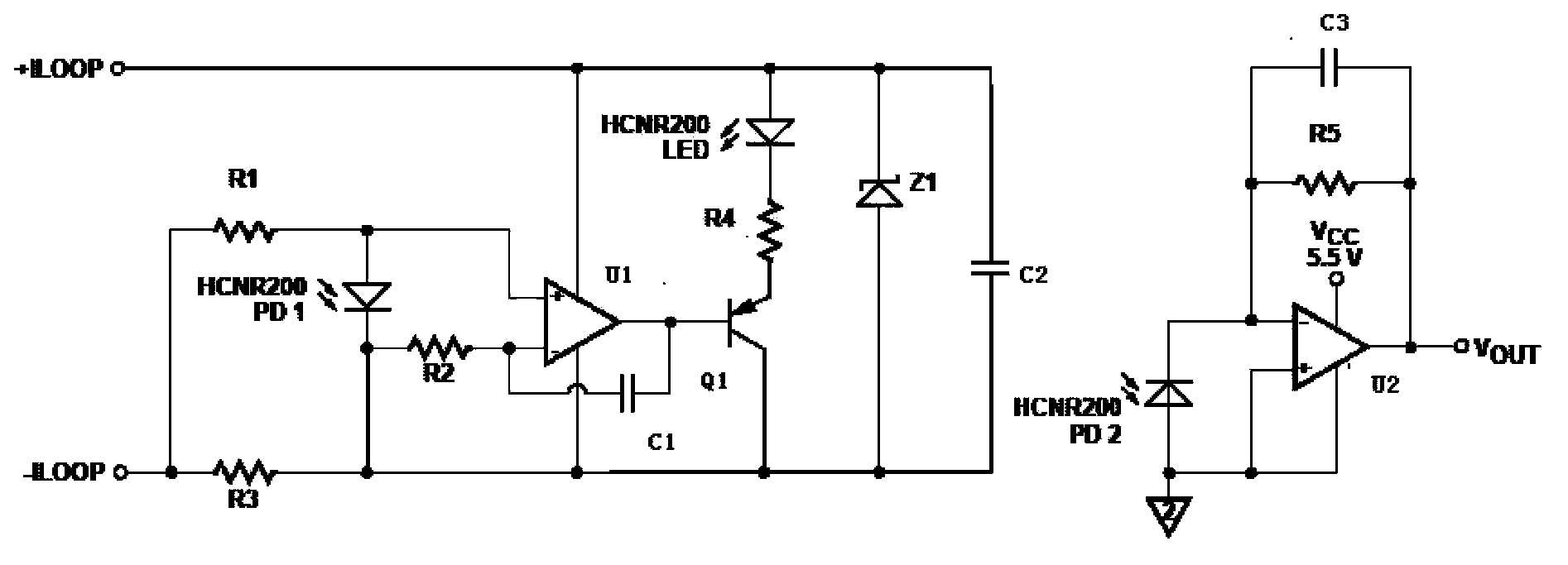
[0043] The output signal of the pressure transmitter is a 4-20mA current signal, so it uses figure 2 Way to make electronic circuit boards. The input end is connected to the output of the pressure transmitter, and the output end is connected to the acquisition system. Choose appropriate electronic components to make the linear coefficient of the optocoupler:

[0044] K3=K1 / K2=1 (1)

[0045] In this way, the relationship between the output voltage Vout and the input current Iloop can be obtained:

[0046] Vout / IlooP=K3*R3*R5 / (R3+R5) (2)

[0047] The applicant chooses R3 and R5 as 25Ω and 80KΩ respectively, so that the input 4-20mA current signal is linearly converted into a 0.8-4V voltage signal
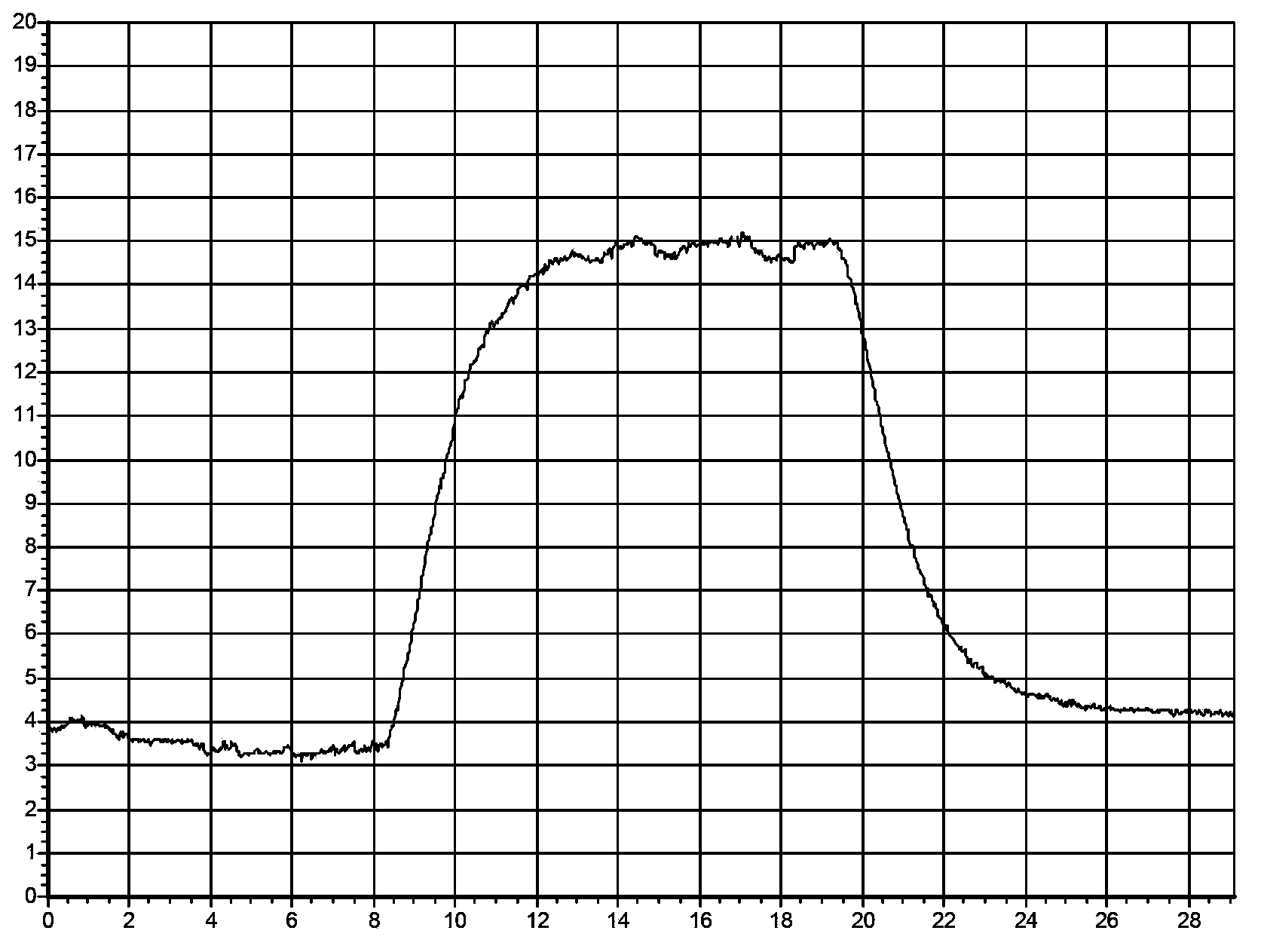
[0048] The invention isolates the interference signal coupled to the pressure transmitter transmission line during the high-power pulse discharge. It effectively reduces the amplitude of strong pulse interference and prevents the damage of the strong pulse interference sig...


PUM


Abstract

The invention discloses a measurement and control system capable of isolating strong impulse interference. The measurement and control system comprises a pressure transmitter, an isolating circuit and a collecting system. The pressure transmitter is connected with a discharging cavity, and is used for measuring the pressure of the gas inside the discharging cavity when a discharging circuit discharges for the gas inside the cavity. The isolating circuit is connected with the output end of the pressure transmitter, and is used for sampling output electrical signals to electrically isolate input signals from the output signals and to achieve linear conversion between the input signals and the output signals. The collecting system is connected with the output end of the isolating circuit, and is used for collecting clear signals output by the isolating circuit to a computer system, and the clear signals are displayed through measurement and control software. According to the measurement and control system, interference signals coupled to a testing signal transmission line are isolated in the period of discharging to high-power impulses, and therefore the amplitude of the interference of strong impulses is effectively reduced, the damage to a testing system from the strong impulse interference signals is prevented, and the signals cannot lose. The measurement and control system has the advantages of being compact and ingenious in structure, safe, reliable, convenient and fast to use and the like.

Description

technical field [0001] The invention relates to a measurement and control system capable of isolating strong pulse interference, which is applied to a high-energy pulse gas laser with a pulse power supply. Background technique [0002] Oxygen-iodine chemical laser is the chemical laser with the shortest wavelength at present. It has the characteristics of high energy, high efficiency, excellent beam quality and low loss fiber transmission efficiency. However, with the in-depth research on the interaction between laser and matter, high-energy pulsed laser has attracted more and more international attention. Studies in cutting, target destruction, oil drilling, etc. have confirmed that with appropriate pulse frequency and laser energy, the plasma effect and nonlinear effect caused by high-energy continuous wave laser on the surface of the material can be avoided, and the penetration depth is deeper and the speed is higher. faster. Continuous wave high-power laser will produc...

Claims


Application Information

Patent Timeline
IPC IPC(8): G01R31/00
Inventor 于海军李国富多丽萍金玉奇桑凤亭汪健王增强
Owner DALIAN INST OF CHEM PHYSICS CHINESE ACAD OF SCI
Why Eureka
Try Eureka