An acquisition and tracking system based on a relay terminal and an on-orbit phase calibration method

A tracking system and phase calibration technology, which is applied in relay system monitoring, transmission system, radio transmission system, etc., can solve the problems of low phase calibration accuracy, high real-time performance, and many participating devices, and achieve high phase calibration accuracy and crossover The effect of small coupling items and strong real-time performance

Active Publication Date: 2016-06-29
XIAN INSTITUE OF SPACE RADIO TECH
View PDF3 Cites 0 Cited by
  • Summary
  • Abstract
  • Description
  • Claims
  • Application Information

AI Technical Summary

Problems solved by technology

[0007] 1) The phase calibration process is complicated: the satellite-ground system equipment participates in the calibration, or establishes a ground calibration tower for phase calibration. The calibration process involves many equipment, high cost, and complex system
[0008] 2) The accuracy of phase calibration is not high: the higher bits of the phase shifter are used for phase adjustment to achieve the phase consistency of the sum signal Σ and the difference signal Δ, the phase calibration accuracy is low, and the residual part of the cross-coupling term
[0009] 3) Poor real-time performance and poor repeatability: the method of establishing a calibration tower is adopted, and the repeatability of the equipment is poor after launch
The ground tracking accuracy analysis method has a certain hysteresis and cannot realize real-time automatic phase calibration on orbit
[0010] Therefore, the traditional phase calibration method is not applicable, and cannot meet the task requirements of simple and easy phase calibration of relay terminals, high precision, small coupling, high real-time performance, and strong repeatability

Method used


Image

  • An acquisition and tracking system based on a relay terminal and an on-orbit phase calibration method
  • An acquisition and tracking system based on a relay terminal and an on-orbit phase calibration method
  • An acquisition and tracking system based on a relay terminal and an on-orbit phase calibration method

Examples


Embodiment Construction

[0042] Specific embodiments of the present invention will be further described in detail below in conjunction with the accompanying drawings.

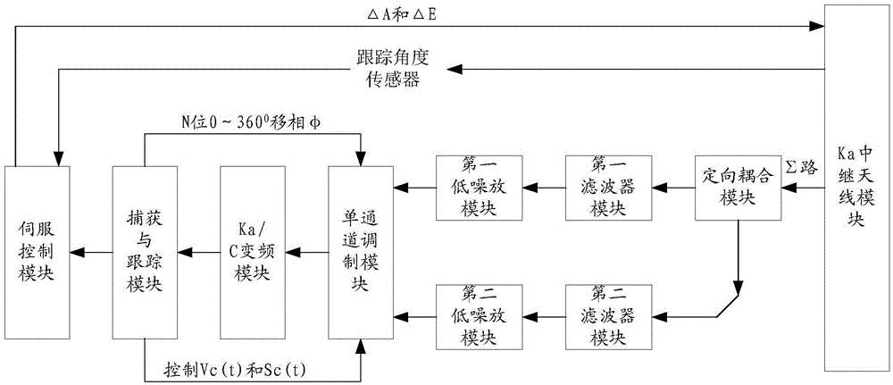
[0043] The present invention provides a capture and tracking system based on relay terminals, such as figure 1 As shown, including: Ka relay antenna, directional coupler module, first filter module, second filter module, first low noise amplifier module, second low noise amplifier module, single channel modulation module, Ka / C frequency conversion module, capture and track module, and servo control module. The Ka relay antenna includes a feed that includes a TE 11 coupler, the Ka-band single beacon signal input from the outside passes through the TE 11 Coupler formation and signal.

[0044]The Ka relay antenna receives the single beacon signal of the external Ka frequency band and outputs the sum signal to the directional coupler module. The directional coupler module divides the sum signal into two paths according to the coupling c...


PUM


Abstract

An acquisition and tracking system based on a relay terminal and an on-orbit phase calibration method, the system includes a Ka relay antenna, a directional coupler module, a first filter module, a second filter module, a first low-noise amplifier module, a second Low noise amplifier module, single channel modulation module, Ka / C frequency conversion module, capture and tracking module and servo control module. The on-orbit phase calibration method uses the characteristics of the pitch and azimuth orthogonality, and the pitch is 90° ahead of the azimuth. When the single-channel modulation module and the channel N phase shifter change linearly from 0° to 360°, the relative difference between the sum and difference channels is calculated. Phase error, and on-orbit automatic angle compensation. Compared with the method of using ground calibration tower phase calibration and setting a fixed phase value in the existing satellite technology, the present invention ensures the accuracy of angle compensation, improves the simplicity, real-time and repeatability of phase calibration, and reduces the Error cross-coupling term due to phase difference.

Description

technical field [0001] The invention relates to an acquisition and tracking system based on a relay terminal and an on-orbit phase calibration method, which are mainly used in various low-orbit spacecraft relay acquisition and tracking systems, and belong to the technical field of satellite radio tracking and measurement. Background technique [0002] The Σ and Δ signals formed by the target signal entering the antenna pass through a long channel respectively. When reaching the single-channel modulator, the phase relationship between Σ and Δ often changes over time due to changes in various factors such as temperature and circuit parameters. That is, it is not possible to maintain the adjusted phase relationship all the time. [0003] This relative phase change of the sum and difference will cause the azimuth and pitch error characteristics to deteriorate, such as the slope of the error characteristic curve becomes smaller, the polarity of the error characteristic changes, a...

Claims


Application Information

Patent Timeline
Patent Type & Authority Patents(China)
IPC IPC(8): H04B7/185H04B17/40
Inventor 赵鸿王宏卓彭碧玉李静澜朱宝骏
Owner XIAN INSTITUE OF SPACE RADIO TECH
Why Eureka
Try Eureka