
Multifunctional sintering blowing ring circular cooler

A ring cooler and multi-functional technology, applied in the field of metallurgical equipment, can solve the problems of large dust, reduce the efficiency of waste heat utilization, and pollute the surrounding environment, and achieve the effects of simple sealing structure, improved sealing effect, and increased ventilation area

Active Publication Date: 2014-02-26
MCC NORTH (DALIAN) ENG TECH CO LTD
View PDF8 Cites 7 Cited by
  • Summary
  • Abstract
  • Description
  • Claims
  • Application Information

AI Technical Summary

Problems solved by technology

Problem: Because the rubber material is easily damaged and the temperature resistance is insufficient, the initial sealing effect is usually acceptable, and the long-term air leakage is serious, and the air leakage rate will reach 40%-50%, which not only wastes a lot of energy, but also seriously pollutes the bulk material blown out of the air leakage The surrounding environment is polluted, and the service life of rubber parts is also very short, resulting in a lot of waste;
[0006] 2. The sealing effect between the trolley railing on the upper part of the trolley and the cover of the ring cooler is not good
Due to the high temperature of the exhaust gas after heat exchange in the 1 and 2 cooling sections, usually 300°C-400°C, at the same time, considering the optimal process of waste heat power generation, in order to improve the efficiency of waste heat utilization, the 1st and 2nd cooling sections of the ring cooler will also take The heated low-temperature exhaust gas is used as cooling air to pass into the lower part of the ring cooler trolley again to form a hot air circulation system to increase the temperature of the hot exhaust gas. Therefore, the seal here needs to use high-temperature resistant rubber as the sealing element, and the equipment cost will be greatly increased. ;
[0007] 3. The heat dissipation of the ring cooler is large. The traditional ring cooler trolley railing and cover are not pre-heated and insulated from the atmosphere. A large part of the heat is radiated into the surrounding air through radiation, making the ring cooler The air temperature near the walking platform of the 1st and 2nd cooling section of the chiller is very high, it is difficult for maintenance personnel to approach, and a lot of energy is wasted;
[0008] 4. There is a lot of dust around the ring cooler and the environment is harsh. Due to the poor sealing effect and the upper cover of the ring cooler except for the seal between the 1st and 2nd cooling sections and the trolley, the rest of the upper cover is only a rainproof herringbone cover. The dust in the exhaust gas of the remaining cooling sections diffuses around the ring cooler, causing pollution to the surrounding environment
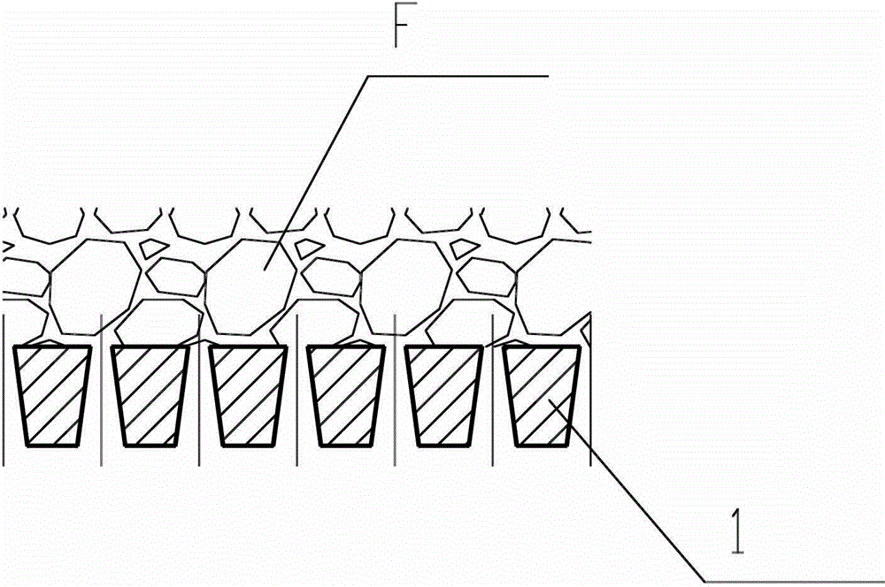
Problem: trolley 1 is an integral casting structure, which is difficult to meet the needs of large-scale equipment, and its ventilation hole form is the same as that of the pellet ring cooler trolley, such as image 3 The section shown is an inverted trapezoidal geometric shape. There are 4 gaps around the trolley 1. In order to ensure that the trolley can turn freely, each gap needs to have a certain width.
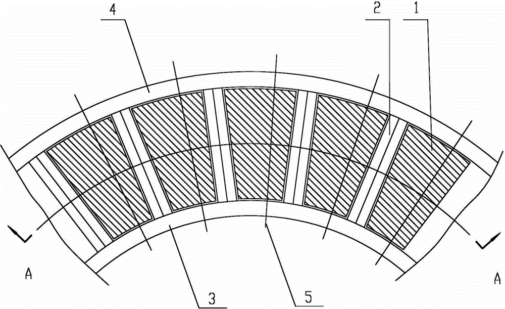
[0012] 2. The effective ventilation area is small, such as figure 2 As shown, the triangular connecting beam 2 is used to connect the inner and outer slewing frames 3 and 4. Due to structural limitations, this triangular connecting beam 2 is an unventilated component. Its existence reduces the ventilation area of ​​the ring cooler and improves the cooling effect. reduce
The triangular connecting beam also prevents the trolleys from being connected end to end in sequence in the circumferential direction, adding a material leakage gap, which increases the amount of bulk material, and one of the gaps currently does not have a good structure to reduce the leakage of bulk material;
[0013] 3. The seal between the lower part of the rotary body and the bellows is achieved by means of the bottom surface of the rotary frame. The seal is usually made of rubber composite material. Although the sealing effect is better than that of the traditional ring cooler, the resistance at the seal is too large, and the ring cooler About half of the power consumption is used to overcome the frictional resistance at the seal;
Problem: Although the overall performance of rubber composite materials is better than that of rubber, it also shows problems such as easy damage and insufficient temperature resistance (the high-temperature exhaust gas temperature of the ring cooler is generally 300°C-400°C). The initial sealing effect is often acceptable, and the long-term The operation leakage is serious, as high as 30% to 50%. A large amount of heat energy is lost to the air in vain, which reduces the efficiency of waste heat utilization, and the dust emitted along with it also pollutes the surrounding environment.
Moreover, in order to prevent air leakage, the tight fit between the sealing element and the fixing frame also leads to an increase in the sealing resistance and increases the power consumption of the equipment.
The sealing effect is not ideal

Method used


Image

  • Multifunctional sintering blowing ring circular cooler
  • Multifunctional sintering blowing ring circular cooler
  • Multifunctional sintering blowing ring circular cooler

Examples


Embodiment Construction

[0058] The present invention will be described in detail below in conjunction with the accompanying drawings.

[0059] Such as Figure 4-20 As shown, the multifunctional sintering blast ring type annular cooler of the present invention comprises an annular cooler frame 12, an inner support roll 23 and an outer support roll 14 connected to the annular cooler frame 12, through the inner support roll 23 and The inner slewing frame 4 and the outer slewing frame 3 supported by the outer support roller 14 are arranged between the inner slewing frame and the outer slewing frame and the connecting beam 2 connecting the two is arranged between the inner slewing frame 4 and the outer slewing frame 3 The trolley 1, the trolley shaft 5 connecting the trolley 1 with the inner slewing frame 4 and the outer slewing frame 3, and the inner trolley fence 21 and the outer trolley fence respectively connected with the inner slewing frame 4 and the upper part of the outer slewing frame 3 The plat...


PUM


Abstract

The invention relates to a multifunctional sintering blowing ring circular cooler comprising a cooler frame, inner and outer support rolls, inner and outer rotating frames, a connecting beam, a trolley, a trolley shaft, inner and outer trolley panels, a U-shaped sealing hood, a transmission device, first inner and outer seals, and second inner and outer seals. The multifunctional sintering blowing ring circular cooler is characterized in that the section of the connecting beam is in the shape of a round tubular part, two ends of the connecting beam are connected with sides, in contact with material, of the lower portions of vertical plates, close to the sintering trolley, of the inner and outer rotating frames respectively, the first and outer seals are composed of U-sectioned inner and outer sealing channels disposed on a bellows frame, particles disposed in the inner and outer sealing channels, and inner and outer circular sealing plates, one ends of the inner and outer circular sealing plates are fixedly connected with the inner and outer rotating frames of the sintering trolley respectively, the other ends of the inner and outer circular sealing plates are inserted into the particles in the inner and outer sealing channels respectively, and the second inner and outer seals are lap seals. The multifunctional sintering blowing ring circular cooler has the advantages of good airtightness, energy saving, and environmental friendliness.

Description

technical field [0001] The invention belongs to the technical field of metallurgical equipment, and in particular relates to a multifunctional sintering blast ring type ring cooler. Background technique [0002] The blast ring cooler is one of the important equipments in the sintering production process, which is used to cool the hot sintered ore roasted by the sintering machine and crushed by the single roll crusher. The traditional annular cooler originated in the 1950s. After years of production and application practice, its function and structure have shown many unsatisfactory places, especially in today's advocacy of low-carbon environmental protection, energy saving, and clean production. The problem is becoming more and more prominent, and it is also urgent to provide a multifunctional annular cooler that can not only meet the cooling function, save energy, but also efficiently recover waste heat, and is clean and environmentally friendly. [0003] The core structure...

Claims


Application Information

Patent Timeline
Patent Type & Authority Applications(China)
IPC IPC(8): F27D15/02
Inventor 王晶萍张忠波张永涛施荣陈沙沙
Owner MCC NORTH (DALIAN) ENG TECH CO LTD
Learn More