layered fuel distributor

A fuel distributor, layered technology, applied in the direction of machines/engines, fuel injection devices, engine components, etc., can solve the problems of limited number of oil outlets, high precision and high price, and inability to flexibly control the pressure, so as to reduce the The possibility of mutual seizure, the improvement of reliability, and the effect of expanding the power and application range of matching machines

Active Publication Date: 2016-03-30
CHINA FAW LIMITED WUXI FUEL INJECTIONEQUIP RES INST +1
View PDF6 Cites 0 Cited by
  • Summary
  • Abstract
  • Description
  • Claims
  • Application Information

AI Technical Summary

Problems solved by technology

In this invention, the oil outlet holes of the distributor are evenly distributed on a circular section. Due to the balance of the oil supply duration and sealing, it cannot match the engine with more cylinders, and the detailed oil circuit control is not published in this invention. The structure of the two actuators, and the mutual cooperation structure and phase relationship between the two solenoid valve devices and the distributor have not been announced.
[0010]The above-mentioned electric control distribution pump systems all have a fuel distributor at their core, and the oil outlet holes of the distributor are evenly distributed on a single circular section, because of limited The circumference of the circumference and the fuel injection need to have a certain duration, which makes it difficult to arrange multiple oil outlet holes on the circumference, so this kind of distribution pump is very difficult to match and apply to engines with more than 6 cylinders
[0011] Aiming at the scope of application of machine matching, in the invention of the publication number CN1786457A titled "Preset High Pressure Distribution Fuel Injection Pump", it utilizes the processing of pre-spray holes and multiple spray holes on the distribution rotor shaft, and opens by adjusting the chute and the spray holes The cross-sectional area is used to roughly adjust the oil volume, which cannot achieve precise control of the oil volume under variable working conditions, especially the pressure cannot be flexibly controlled, and high emission requirements cannot be achieved without the use of accumulator structure and electronic control technology
[0012]The oil supply system adopts a mechanical distribution device. Due to the limitation of the lift of the end face cam, the injection pressure and the circumferential phase cannot be arranged too many oil outlet holes to affect the distribution of the machine. range of working conditions; the oil supply system using the upgraded electronically controlled distribution device, although its oil outlet pressure is increased, there is still the restriction of the number of oil outlet holes arranged in a single layer; the electronically controlled high-pressure common rail system requires Multiple sets of high-precision and high-priced electronically controlled fuel injectors to improve performance and emissions

Method used


Image

  • layered fuel distributor
  • layered fuel distributor
  • layered fuel distributor

Examples


Embodiment Construction

[0056] The following combined with the attachment is further explained to the present invention.

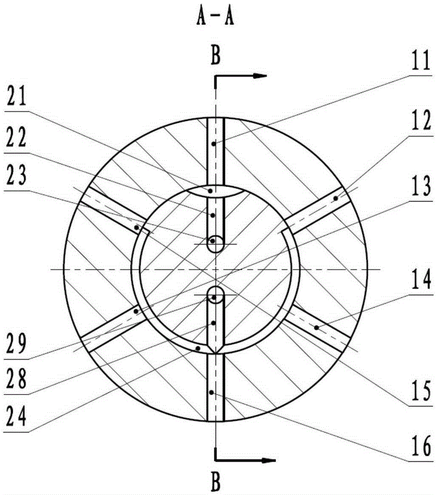
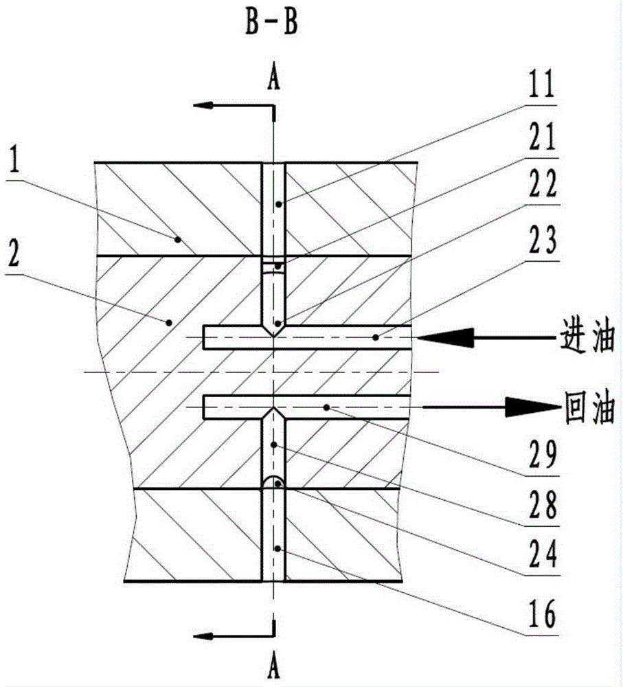
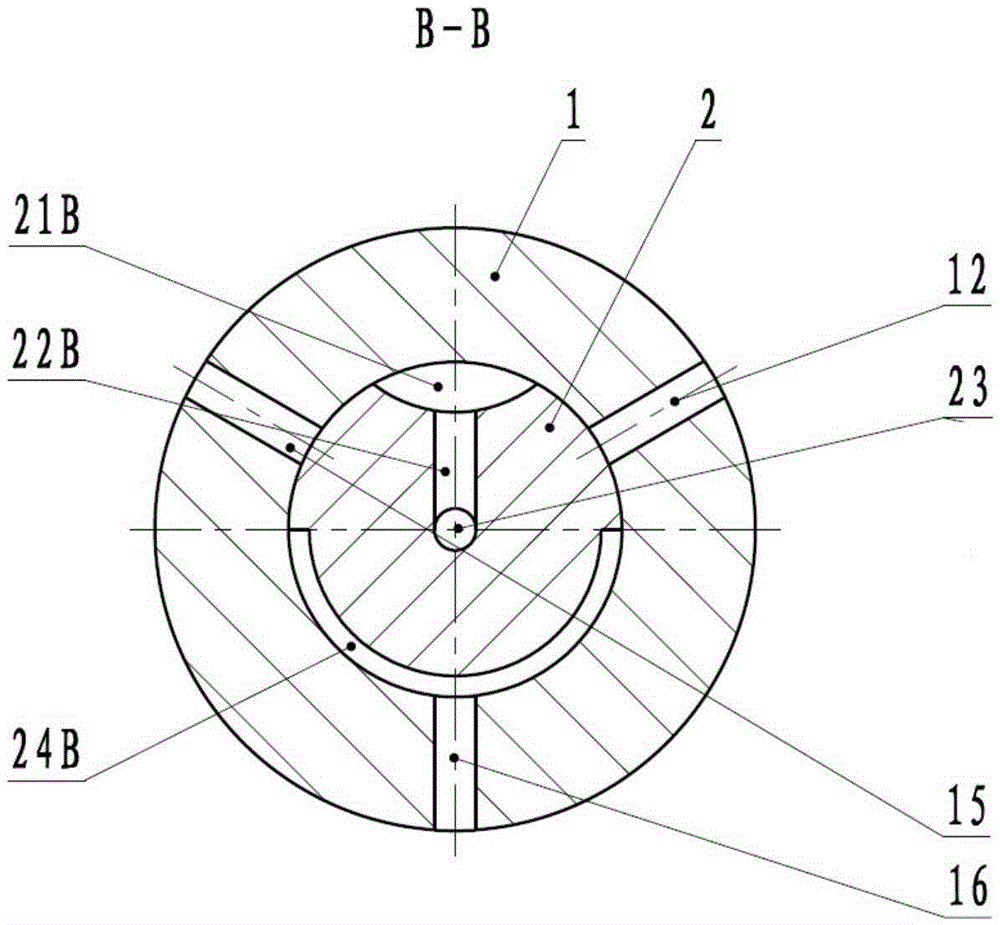
[0057] The core of the invention announced a layered fuel distributor is that the allocation of the stator out of the oil pores are divided into multi -layer layout according to the number of cylinders, and the allocation of the rotor out of the oil holes for pairing design.

[0058] First introduce the working principle of the existing distribution device, and then introduce the specific details of the layered fuel distributor proposed by the present invention.

[0059] Figure 1A and Figure 1B The 6 -cylinder engine is displayed with an existing distribution of an existing distribution in the principle of layering.It can be seen that the figure shows that when the distribution of the allocation rotor in the assignment rotor 23 The fuel passing the fuel pores 22 to the distribution of the rotor out of the oil cavity is distributed into the allocation of the allocation of stator 1 ou...


PUM


Abstract

The invention discloses a layered fuel distributor, which includes a distribution rotor, a distribution stator and a casing. The distribution rotor rotates in the distribution stator, and the oil outlet holes of the distribution stator are divided into multiple layers, and the distribution rotor has the same number of radial distribution rotor oil outlet holes as the number of layers of the distribution stator; The number is the same, the number of layers matches the number of cylinders of the engine, and the number of cylinders is an integer multiple of the number of layers; the oil inlet channel of the distribution rotor is also used as the oil return channel, that is, the oil supply and oil return of the layered fuel distributor are Shared oil passage and can be continuous. The layered fuel distributor has doubled the available phases of oil supply and oil return. The increase of the oil supply phase broadens the power range, and the increase of the oil return phase prolongs the available oil return time to provide support for emission compliance.

Description

Technical field [0001] The invention involves an electronic control high -voltage fuel system for an internal combustion engine, especially a layered fuel distributor. Background technique [0002] Energy -saving and emission reduction are the two major driving force for the development of the technology of internal combustion engine today.The developed countries in the world have implemented strict discharge regulations on internal combustion engines since the early 1990s, and the regulations of time have become more and more harsh over time.Among them, the fuel system is the core technology where the car meets the higher emissions standard. The mainstream development trend of the fuel system is to develop towards high -voltage injection, multiple injection, and electronic control spraying directions. ThereforePersons' research on high -pressure fuel systems.At present, the engine fuel system is generally upgraded from mechanical pumps to electronic control pumps, and the electr...

Claims


Application Information

Patent Timeline
Patent Type & Authority Patents(China)
IPC IPC(8): F02M41/00
Inventor 王健陈希颖黄俊居钰生夏少华刘志华杨晓锋
Owner CHINA FAW LIMITED WUXI FUEL INJECTIONEQUIP RES INST
Why Eureka
Try Eureka