Manufacturing method of optical fiber F-P cavity sensor and manufacturing device thereof

A production device, F-P technology, applied in the direction of optical device transmission of sensing components, optical waveguide coupling, etc., can solve the problems of poor sealing performance, inability to withstand high temperature strength, and inapplicability, and achieve uniform angular stress and sealing performance Good, guarantee the effect of reliability

Active Publication Date: 2014-03-19
LASER RES INST OF SHANDONG ACAD OF SCI
View PDF6 Cites 10 Cited by
  • Summary
  • Abstract
  • Description
  • Claims
  • Application Information

AI Technical Summary

Problems solved by technology

[0004] The welding of the optical fiber F-P cavity is mainly to fix the optical fiber inserted into the capillary glass tube and the capillary glass tube. In "Wavelength Modulated Source", epoxy resin glue is used to bond the optical fiber and capillary. Because the epoxy resin glue is unstable at high temperature and has creep, the performance of the optical fiber F-P cavity glued by epoxy resin is unstable, cannot withstand high temperature and has poor strength. , poor sealing performance and other shortcomings, it cannot be applied to the harsh environment of oil wells
In the literature "Study on the packaging method of optical fiber F-P interferometer sensor", the single-side high-frequency CO2 pulse laser thermal fusion fixation method is used. Due to the uneven force at the solder joint, this method is easy to cause the capillary glass tube to bend and deform at the solder joint. In addition, due to only one-sided heat fusion, even if the optical fiber is welded to the glass tube, it cannot guarantee complete sealing
In the document "Fiber Optical pressure and temperature sensors for oil down hole application", three CO2 laser beams forming 120° thermal fusion method are used to fix the optical fiber and capillary glass tube, but due to the small diameter of the capillary glass tube, very fine adjustment is required , the system requires high precision and the cost of building the system is high

Method used


Image

  • Manufacturing method of optical fiber F-P cavity sensor and manufacturing device thereof
  • Manufacturing method of optical fiber F-P cavity sensor and manufacturing device thereof
  • Manufacturing method of optical fiber F-P cavity sensor and manufacturing device thereof

Examples


Embodiment 1

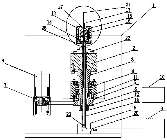
[0032] Such as Figure 1-2 As shown, a manufacturing device of an optical fiber F-P cavity sensor, it includes a device bracket 1 provided with a fixing seat 5, in which a tapered roller bearing 4 is fixed; the top of the hollow fixed shaft 3 and the hollow three-claw clamp The disk 2 is fixedly connected; the middle part of the fixed shaft 3 passes through the tapered roller bearing 4 and is supported and fixed on the device bracket 1 and pivots around the axis of the fixed shaft 3 relative to the device bracket 1. The bottom of the fixed shaft 3 is fixedly connected with the large synchronous pulley 6 ;; The small synchronous pulley 7 driven by the large synchronous pulley 6 and the stepper motor 8 is driven by a belt; the hollow tube shaft 18 passes through the center of the three-jaw chuck 2 and the fixed shaft 3, and the upper part of the tube shaft 18 is clamped by the three-jaw The disc 2 is clamped and rotated with the three-jaw chuck 2. The lower end of the tube shaft...

Embodiment 2

[0035] The similarities between this embodiment and Embodiment 1 will not be repeated, and the difference is that it is a method for manufacturing an optical fiber F-P cavity sensor, which uses the manufacturing device for an optical fiber F-P cavity sensor described in Embodiment 1, which includes the following step:

[0036] (1) Set up the welding system device, fix the tapered roller bearing 4 in the fixed seat 5, extend the fixed shaft 3 into the three-jaw chuck 2 and the tapered roller bearing 4 and fix it, and use the fastening nut 12 to secure the large synchronous The pulley 6 is fixed in position, and the small synchronous pulley 7 and the stepping motor 8 are connected, and the tube shaft 18 is inserted into the gap between the three-jaw chuck 2, the fixed shaft 3 and the tapered roller bearing 4, and inserted into the base of the tube shaft In 19, the tube shaft 18 and the tube shaft base 19 realize dynamic sealing through the sealing ring 23, and the tube shaft bas...


PUM


Abstract

The invention provides a manufacturing device of an optical fiber F-P cavity sensor and a manufacturing method thereof. The manufacturing device comprises a bracket, a stepping motor, large and small synchronous belt wheels, a three-jaw chuck, a tapered roller bearing, a vacuum pump, an oxyhydrogen flame hot melting machine, and a capillary glass tube clamp. One end of a capillary glass tube is welded by oxyhydrogen flame, the other end of the capillary glass tube is inserted into a fiber, and the capillary glass tube is inserted into the capillary glass tube clamp. A tail fiber passes through a tube shaft and is fixed and sealed by a rubber washer and a fixing nut. The rotating speed is in a range of 120r / min to 140r / min. The heating of the capillary glass tube is uniform. The vacuum pump is connected with a tower joint and the capillary glass tube is pumped into vacuum while the clamp is rotated. At the same time, the capillary glass tube is heated and melted by the oxyhydrogen flame hot melting machine, and under the effect of pumping, a capillary glass tube wall is collapsed inward to melt the fiber with the capillary glass tube. According to the melting method, the capillary glass tube and the fiber are firmly melted, the sealing performance is good, the penetration of oil and moisture from a welding point to damage an F-P cavity can be effectively prevented, and a solid foundation is laid for the long-term application of the optical fiber F-P cavity sensor in a harsh environment.

Description

technical field [0001] The invention belongs to the technical field of optical fiber sensors, and relates to a manufacturing method of an optical fiber pressure sensor, in particular to a manufacturing method and a manufacturing device of an optical fiber F-P cavity pressure sensor. Background technique [0002] In the process of oilfield development, it is necessary to monitor downhole temperature, pressure and other parameters in real time to understand the physical state of the downhole to optimize the oil recovery plan and improve oil recovery efficiency. Due to the harsh environment downhole, traditional electronic sensors cannot work stably for a long time downhole. Optical fiber Sensors are more and more widely used due to their strong anti-interference ability, corrosion resistance, and good reliability. [0003] In 1991, Murphy et al. produced the F-P fiber optic sensor, which is characterized in that two bare optical fibers with flattened ends are placed in a colli...

Claims


Application Information

Patent Timeline
Patent Type & Authority Applications(China)
IPC IPC(8): G01D5/26G02B6/255
Inventor 王英英郭士生王昌刘小会赵庆超赵文安尚盈吕京生翟瑞占
Owner LASER RES INST OF SHANDONG ACAD OF SCI
Why Eureka
Try Eureka