A HEMT gate leakage current separating structure and method based on capacitor structure

A technology of capacitive structure and current separation, applied in the direction of measuring current/voltage, circuit, measuring electricity, etc., can solve difficult problems, achieve reliable results, easy to implement, and simple structure

Active Publication Date: 2014-03-19
XIDIAN UNIV
View PDF6 Cites 6 Cited by
  • Summary
  • Abstract
  • Description
  • Claims
  • Application Information

AI Technical Summary

Problems solved by technology

This also brings certain difficulties to further research on material growth and device process optimization related to HEMT devices, as well as device failure mechanism research and performance evaluation.

Method used


Image

  • A HEMT gate leakage current separating structure and method based on capacitor structure
  • A HEMT gate leakage current separating structure and method based on capacitor structure
  • A HEMT gate leakage current separating structure and method based on capacitor structure

Examples


Embodiment Construction

[0028] The present invention will be further described below in conjunction with accompanying drawing and specific embodiment:

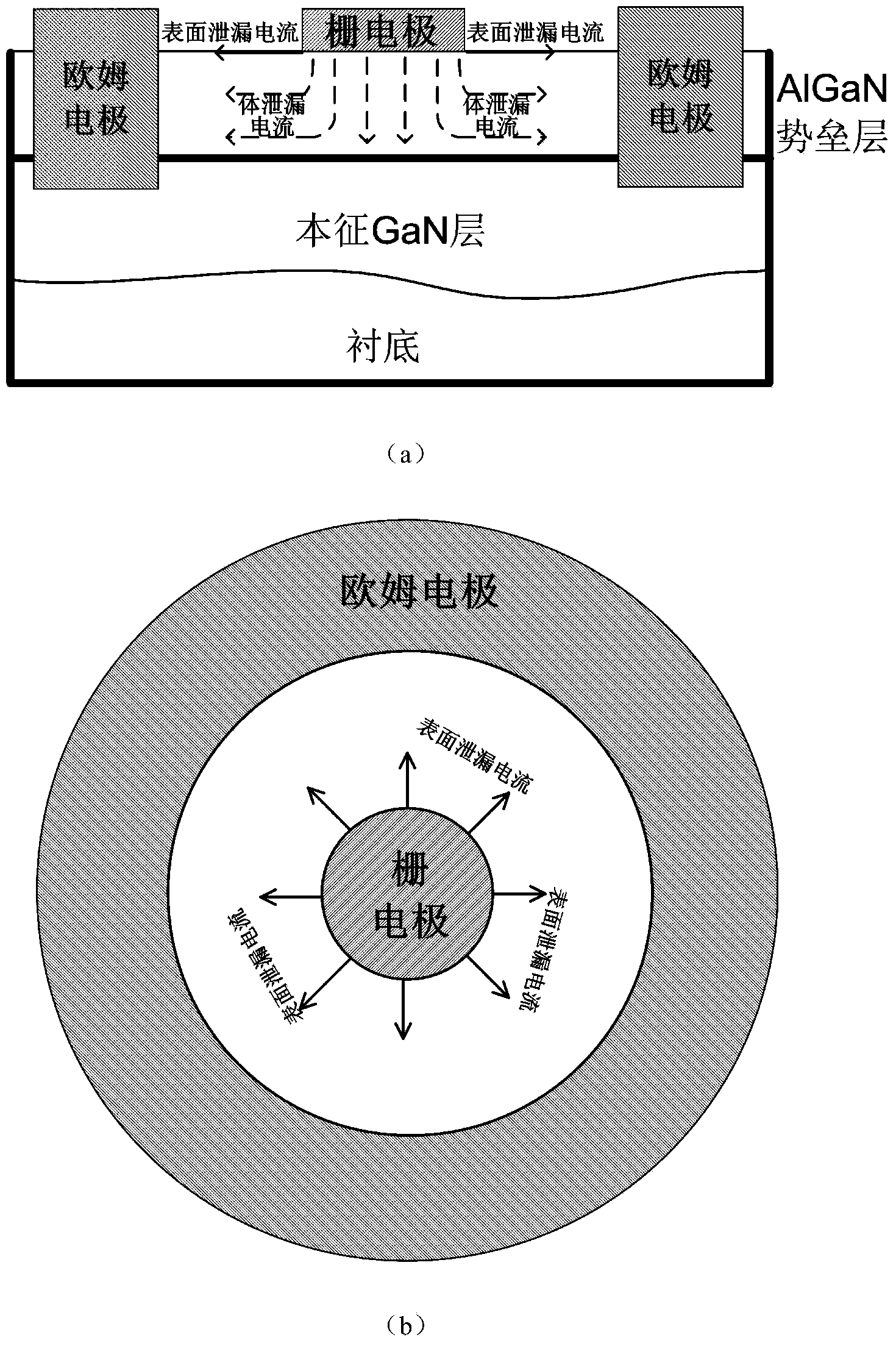
[0029] figure 1 It is a schematic diagram of the gate leakage current components in the ring structure HEMT, (a) cross-sectional view, (b) top view. A typical ring structure HEMT includes two electrodes: a Schottky gate electrode (SchottkyGate) and an ohmic electrode (Ohmic). The gate leakage current of HEMT devices is an important factor affecting device characteristics. As shown in Figure (a), the gate leakage current of HEMT devices mainly includes two parts: the lateral surface leakage current between the Schottky gate and the ohmic contact (I surf ) and the bulk leakage current through the barrier layer perpendicular to the Schottky gate surface (I bulk ); Figure (b) is the top view of the annular HEMT structure, the surface leakage current I surf It is mainly generated by the high electric field between the Schottky gate electrode and the o...


PUM


Abstract

The invention discloses a HEMT gate leakage current separating structure and method based on capacitor structure. The HEMT grid leakage current separating structure comprises two annular schottky gate capacitors with different areas. Each capacitor is configured in dual-end structure and comprises a gate electrode and an ohmic electrode. The radius of the gate electrode of the first capacitor is R1. The Schottky gate of the second capacitor is annular. The radius of the outer ring of the Schottky gate of the second capacitor is R1 while the radius of the inner ring of the Schottky gate of the second capacitor is 0.707R1. The two Schottky capacitors have same distance between the gate electrode and the Ohmic electrode, wherein the distance is equal to R2-R1. The method comprises using a conventional semiconductor parameter testing device to perform an electrical test on the two capacitors so as to achieve quantified separation of body leakage current and surface leakage current in the gate leakage current of a HEMT device. The HEMT gate leakage current separating structure and method have characteristics of simpleness and reliable results and can be widely used in material growth, device process optimization, and subsequent reliability assessment of the HEMT device.

Description

Technical field: [0001] The invention belongs to a HEMT gate leakage current separation structure and method based on a capacitance structure. Background technique: [0002] GaN materials have good electrical properties, such as wide band gap, high breakdown electric field, high thermal conductivity, corrosion resistance, radiation resistance, etc., and are known as the third-generation semiconductor materials, especially when compared with AlGaN and other materials. The formed heterostructure transistor (HEMT) has a high-concentration and high-mobility two-dimensional electron gas at the heterojunction interface, which has great advantages in the production of high-frequency, high-temperature, high-voltage, high-power electronic devices and microwave devices. and application prospects. In recent years, researchers at home and abroad have carried out extensive and in-depth research on HEMT devices, and have made great progress. [0003] Although GaN-based HEMT devices have...

Claims


Application Information

Patent Timeline
Patent Type & Authority Applications(China)
IPC IPC(8): H01L29/92H01L23/544G01R19/00G01R31/26
CPCH01L29/92G01R31/2621H01L23/544
Inventor 郑雪峰范爽郝跃王冲孙伟伟
Owner XIDIAN UNIV
Why Eureka
Try Eureka