Double-speed double-torque crawler type hydraulic cutting drilling machine

A crawler-type, drilling rig technology, applied in rotary drilling rigs, impact drilling, rotary drilling and other directions, can solve the problems of unstable gas supply, high maintenance costs, short service life of air compressors, etc. The effect of stable air volume, low maintenance and replacement cost, and saving manufacturing cost

Inactive Publication Date: 2014-03-26
GUILIN HUALI HEAVY INDS
View PDF7 Cites 11 Cited by
  • Summary
  • Abstract
  • Description
  • Claims
  • Application Information

AI Technical Summary

Problems solved by technology

[0003] 1. The drill pipe power head adopts single-speed and single-torque mode, which cannot adapt to the drilling of rock formations with different hardness, and the efficiency is low; the rotation (cutting) of the drill pipe is controlled by pedals, and the operator is labor-intensive;
[0004] 2. Drilling rigs are mostly driven by steel wire oil cylinders, and some are driven by chains. There is no lubricating device for the chains or wire ropes. The lubrication of the chains and wire ropes can only be done manually. The effect is poor, the wear is fast, and the life is short; in addition, the steel wire oil cylinder is used to advance and lift slowly, the wire rope is easy to break, the life is short, and the maintenance cost is high;
[0005] 3. Some hydraulic cutting drilling rigs with chain propulsion mechanism do not have brakes, and can only be braked by inserting steel rods into the chain, which is easy to cause damage to the machine, and is prone to safety accidents or damage to the machine during transportation or site

Method used


Image

  • Double-speed double-torque crawler type hydraulic cutting drilling machine
  • Double-speed double-torque crawler type hydraulic cutting drilling machine
  • Double-speed double-torque crawler type hydraulic cutting drilling machine

Examples


Embodiment Construction

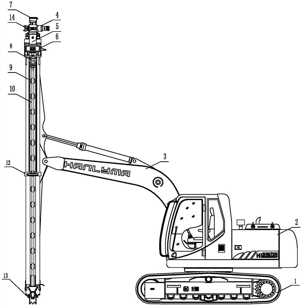
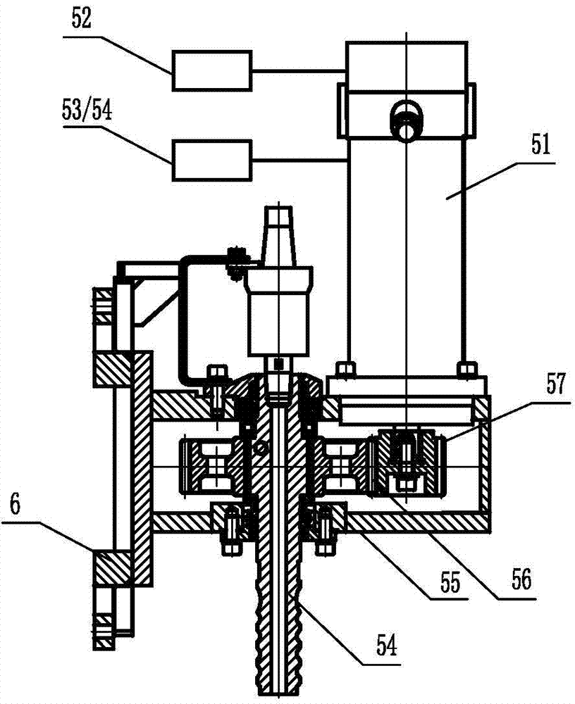
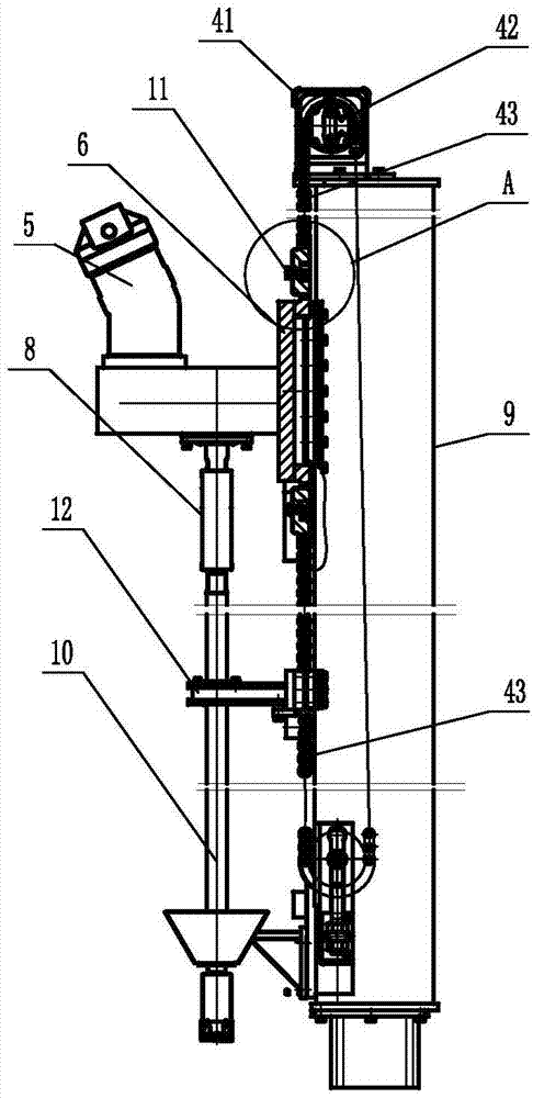
[0046] A double-speed, double-torque crawler-type hydraulic cutting drilling rig, including a boom 3, a drill boom 9 connected to the boom, a power head 5, a propulsion mechanism 4, an air compressor system 2 and a pressure oil source, and the propulsion mechanism is installed On the drill arm, the power head is installed on the guide rail of the drill arm, and the cutting motor 51 installed in the power head is connected to the power head shaft 54 ​​and the drill pipe 10 through the gearbox assembly. The feeding and lifting of the drill pipe is driven by the drive; the main components of the air compressor system are installed on the body of the drilling rig, and communicate with the blowing pipeline of the drilling arm through the pipeline installed on the arm of the drilling rig;

[0047] The power head 5 is equipped with a two-speed, two-torque control device 52 and a drill pipe rotation control device. The two-speed, two-torque control device 52 includes a variable solenoi...


PUM


Abstract

Provided is a double-speed double-torque crawler type hydraulic cutting drilling machine. A double-speed double-torque control device and a drill rod rotation control device are arranged in a power head, a chain, a chain wheel and a feed motor with a speed reducer are adopted in a pushing mechanism, an air compressor is a large-air-volume rotary screw air compressor and is provided with a dedicated air storage device and a motor protection device, and an intelligent lubrication system is arranged at the top of a drill arm. The cutting drilling machine can adapt to rock strata of different rigidities, and is high in hole drilling efficiency, drill rod rotation control is easy and convenient, and labor intensity is low. In the hole drilling process, applied pressure is large, rod lifting speed is high, the maintenance of the chain is good, the service life is long, and the maintenance cost is low. The air compressor is simple and compact in transmission structure, large in exhaust air rate, stable in air pressure, smooth in slug discharge and high in efficiency. The motor is stopped smoothly, impact vibration is small, the drill arm and the drill rod are high in strength and good in torque resistance and impact resistance, the drill rod is connected with a power head shaft through a coupling with a buffering function, and the power head shaft, a bearing and a transmission gear can be prevented from being damaged.

Description

technical field [0001] The invention relates to an engineering machine, in particular to a crawler-type hydraulic cutting drilling machine with double-speed and double-torque control modes. Background technique [0002] The existing crawler hydraulic cutting drilling rig has the following problems: [0003] 1. The drill pipe power head adopts single-speed and single-torque mode, which cannot adapt to the drilling of rock formations with different hardness, and the efficiency is low; the rotation (cutting) of the drill pipe is controlled by pedals, and the operator is labor-intensive; [0004] 2. Drilling rigs are mostly driven by steel wire oil cylinders, and some are driven by chains. There is no lubricating device for the chains or wire ropes. The lubrication of the chains and wire ropes can only be done manually. The effect is poor, the wear is fast, and the life is short; in addition, the steel wire oil cylinder is used to advance and lift slowly, the wire rope is eas...

Claims


Application Information

Patent Timeline
IPC IPC(8): E21B7/02E21B3/02E21B21/16E21B19/084E21B44/00E21B17/00E21B17/03F04C23/02F16H57/05
Inventor 周夏南陈宗宜赵慧唐中亮
Owner GUILIN HUALI HEAVY INDS
Why Eureka
Try Eureka